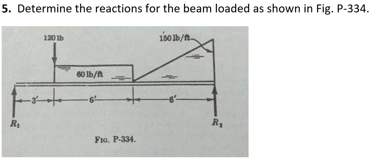
5. Determine the reactions for the beam loaded as shown in Fig. P-334. 150 lb/ft- 120 1b 60 lb/ft 6- R2 R1 FIG. P-334.


Q: Q Determine the reaction of the wall on the beam in fig. below 6000 t 3'
A:
Q: Find the support reactions, draw the free-body diagram of the beams that shows the reactions and the…
A:
Q: 13.1 through 13.4 Determine the reactions and draw the shear and bending moment diagrams for the…
A:
Q: Q1: Determine the Moment of the system shown in Fig (1) about point o? Q2: Calculate the reactions…
A:
Q: SITUATION 2. 1. Determine the reactions or total reaction at C. 2. Determine the reaction at B. 3.…
A:
Q: Three rods are welded together to form a “corner" that is supported by three eyebolts. Neglecting…
A:
Q: 13.9 through 13.12 Determine the reactions and draw the shear and bending moment diagrams for the…
A: To determine the support reactions using the method of consistent deformations and draw the shear…
Q: Determine the reactions at A and B for the given figure. 400 N /m Determine the reactions at A. a.…
A:
Q: 200lb -11. The 200-lb force of Fig. P1-11 acts on the ox B. Resolve the force into two components,…
A:
Q: Qe: For the beam shown in Fig.Qu. Determine the reactions at A and B. Draw F.B.D for the system? 300…
A: FBD-
Q: Section 13.1 13.1 through 13.4 Determine the reactions and draw the shear and bending moment…
A:
Q: The weight of a 5 m long trolley, moving at a constant speed on a beam bridge, is modeled as a…
A: The FBD of the loading is shown below:
Q: Fig. 12.29 shows a pin-jointed frame carrying vertical loads of 1 kN each at the joints B and G and…
A:
Q: 14.1 through 14.8 Determine the reactions and draw the shear and bending moment diagrams for the…
A:
Q: -11. In Fig. P 4-11, bodies A and B remain at rest on smooth planes. The weight of body A is 200 lb.…
A:
Q: 70 kN Q) Analyze the frame shown in Fig.(1), approximately finding all the reactions. Also, draw…
A: portal frame is widely used in civil engineering work to transfer horizontal load to the foundation…
Q: Draw the influence lines for the reactions at the supports and the shear and bending moment at point…
A: Given:- Span AB=20 ftSpan BC=10 ftSpan CD=10 ft To find:- a) Draw influence lines for the reactions…
Q: Determine the reactions for the beam shown in Fig. 13.25 by the method of least work
A: Degree of Indeterminacy : The beam is supported by four reactions.So, the degree of indeterminacy,…
Q: Statics Review Problems Determine the reactions at A and B. 4 kip/ht 3 kip/f 2 kip/ Determine…
A: Given data in question Simply supported beam Cantilever beam Span dimensions of all the beams…
Q: Section 13.1 13.1 through 13.4 Determine the reactions and draw the shear and bending moment…
A:
Q: Load-Shear and Shear-Moment Relationships Requirements 1A. Reactions at the supports 1B. Shear…
A: RA + RC = 40 + 16X3 RA + RC = 88 Moment diagram 40 x 1 +15 - 16 x 3 x 4.5 + Rc x 5 =0 Rc = 32.2…
Q: 4. For the beam shown in Fig.4, draw the qualitative influence lines for (i) Bending moments, Mc…
A: Hi! Thank you for the question As per the honor code, We’ll answer the first question since the…
Q: Q4: For the structure shown in Fig.4, determine the force supported by members BD, DE and CE. B 130…
A: Truss is always a axial member forces structures that resist the forces by axial tension or…
Q: Q1: - Find the moment of couple for system shown in fig (1)? Q2: - Determine the magnitude of the…
A:
Q: For each of the four structures shown in Fig. 1, sketch (on separate diagrams): The points of…
A: Free-body diagrams are diagrams helped to show the relative magnitude and direction of all forces…
Q: P = 31 L= q/4 4P 2P 0.4L 0.2L 0.4L toatoztoar toat toztos t0.21t0.4L †0.4L 10.2L▼ 0.4L 7. Determine…
A:
Q: 6-43* A cylinder is supported by a bar as shown in Fig. P6-43. The weight of the cylinder is 100 lb…
A:
Q: For the frame shown in Fig 2, determine the reactions at A an F and the pin reactions at B on ABC.…
A:
Q: For the building frame shown in Fig. P14.20, determine the arrangements of a uniformly distributed…
A: According to our positive beam symbol convention, a positive bending moment makes the beam concave…
Q: Determine the Reactions of the following structures. b. Draw the Shear and Moment diagram Let P…
A: "Since you have asked multiple question, we will solve the first for you ,if you want any specific…
Q: 6° Tso0 FiG. P 1-10 1-10. Resolve the 300-lb force acting on body OBC in Fig. P 1-10 into two…
A: First of all, we have to calculate the support reaction, After then resolve the force acting at C in…
Q: 4. Determine the reaction at support A for the cantilever beam as shown in Figure 4. If the couple…
A: Determine reaction at A?
Q: Q: The resultant of the force system shown in Fig. (1) is a couple 291.2 Counterclockwise. Determine…
A:
Q: FIG.P3.9 Determine the reactions at the supports for the beam shown 30 kN/m 70 KN ty
A: Note:- Hi! Thank you for the question As per the honor code, We’ll answer the first question since…
Q: 120 lb 150 lb/t 60 lb/ft R1 FIG, P-334.
A: To find the support reactions Always take the moments about the hinge joint (since at the hinge…
Q: Find the support reactions A and B at static equilibrium for the loaded beam showing below in fig…
A: To find Reaction forces in the beam.
Q: 4-31. In Fig. P 4-31, determine the horizontal and vertical components of the reaction at A on…
A: The given system can be solved by using equilibrium equation. The forces acting at any angle on…
Q: 13.4 Determine the reactions and draw the shear and bending moment diagrams for the beams shown in…
A:
Q: Calculate the support reactions. Then, draw the shear force diagram (SFD) and bending moment diagram…
A: Consider the figure,
Q: Draw the influence lines for the reactions at the supports for the beam shown in Fig. P14.12.…
A: An influence line is a curve, the ordinates to which at any point equals the value of some…
Q: Q3: Determine the reactions at A and B for the frame loaded shown in Figure.
A: Solution; The total force on inclined leg=12*(75+100)*8=700 N These forces act at a distance at…
Q: Q.5 Determine the reactions in C member BCD as shown in figure? 6 m B 4 m D 2m 300 kN C
A:
Q: For the following frames, determine reactions than draw NFD, SFD and BMD. 6 t/m` 69. 6t 1.5 4,5m 1.5…
A:
Q: The weight of a car, moving at a constant speed on a beam bridge, is modeled as a single…
A: Given:- The weight of the car = W = 20 kN The position of the car from the starting of the beam…
Q: Determine the magnitudes of the pin reactions at B and C if m = 1000 kg. 1.5 m 1.5 m A B C 0.9 m D
A:
Q: Q3 \ Determine the horizontal and vertical components of reaction at the pins A, B, of the…
A: Draw free body diagram calculate the value of θ sin θ=45θ=sin-10.8θ=53.13o
Q: 4. What are the reactions at E in Fig. 2? 5. What is the reaction at Cin Fig. 2? 6. What is the…
A:
Q: SITUATION 2. 1. Determine the reactions or total reaction at C. 2. Determine the reaction at B. 3.…
A:
Q: Determine the reactions and draw the shear and bending moment diagrams for the beams shown in 14.11…
A:


Trending now
This is a popular solution!

Step by step
Solved in 2 steps with 2 images

- Determine the moment of the force with respect to point A for each of the systems shown in fig . P1-26. The 100-Ib force of Fig. P1-26a id vertical and passes through the center of the rec-tangleDetermine The Reaction At Support B In Units Of Kips.c. Determine the reactions of the fixed support at the right end of the 5-m length beam shown.
- a) Calculate the reactions (N) at each of the two rear wheels... (i) at A. (ii) at B. c) If crate D is removed and the position of crate C remains, calculate the reactions (N) at each of the two front wheels at B. Note: cdb=948 kg(a) Assuming that no loads act in Figure P9.16,compute the reactions if support B is constructed 0.48 in.too low. Given: E = 29,000 kips/in.2, I = 300 in.4. (b) Ifsupport B settles _32 in. under the applied loads, computethe reactions.Determine the reactions and draw the shear and bending moment diagrams for the four-span continuous beam shown in Fig. 15.11(a).
- For the frame and loadings shown P=310 KN, and F=620 1-magnitude of horizontal reaction at E 2- magnitude of vertical reaction at A 3- magnitude of vertical reaction at E 4- magnitude of vertical reaction at C 5- magnitude of horizontal reaction at CDetermine the reactions at the supports and draw the bending moment diagram for the following structure. (Ans : Ax=-6.618, Ay=3.469, Ex=-0.11, Ey=27.178, Fx=-3.272, Fy=19.83, Dy=4.522, MAB=-4.209, MBA=10.331, MBC=-9.964, MCB=6.726, MCD=-11.91, MBE=-0.367, MEB=-0.184, MCF=5.185 )Determine the reactions and draw the shear and bending moment diagrams for the three-span continuous beam shown in Fig. 15.6(a) by the slope-deflection method.
- Find the magnitudes of the pin reactions at A, C, and E caused by the 180-lb · ft couple.Q3: Determine the reactions at A and B for the frame loaded shown in Figure.Find the support reactions, draw the free-body diagram of the beams that shows the reactions and the equivalent loadings of the beams. Show the computation where M0 = 1,220 N-m, P = 2650 N, w0 = 1702 N/m, a = 2 m, b = 1.5 m, c = 3.5 m, d = 1.5 m