5052 ww A' 10V 7592 2552 W ob 1002 W Figure 8.3. Circuit 1 oa €1022 10Ω
5052 ww A' 10V 7592 2552 W ob 1002 W Figure 8.3. Circuit 1 oa €1022 10Ω

Delmar's Standard Textbook Of Electricity
7th Edition
ISBN:9781337900348
Author:Stephen L. Herman
Publisher:Stephen L. Herman
Chapter29: Dc Generators
Section: Chapter Questions
Problem 16RQ: Explain the difference between cumulative- and differential-compounded connections.

Related questions
Question
100%

Transcribed Image Text:VI. DATA AND RESULTS:
circuit
1
2
I
Eo
Ro
I'
%diff.
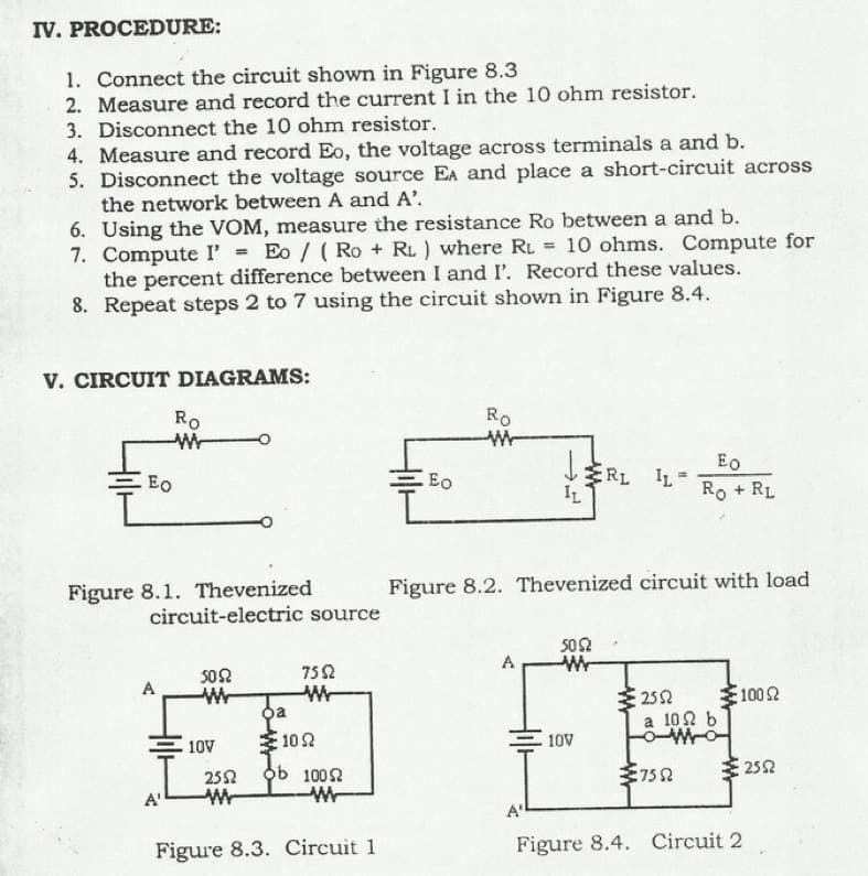
Transcribed Image Text:IV. PROCEDURE:
1. Connect the circuit shown in Figure 8.3
2. Measure and record the current I in the 10 ohm resistor.
3. Disconnect the 10 ohm resistor.
4. Measure and record Eo, the voltage across terminals a and b.
5. Disconnect the voltage source EA and place a short-circuit across
the network between A and A'.
6. Using the VOM, measure the resistance Ro between a and b.
7. Compute I' = Eo / (Ro + RL) where RL = 10 ohms. Compute for
the percent difference between I and I'. Record these values.
8. Repeat steps 2 to 7 using the circuit shown in Figure 8.4.
V. CIRCUIT DIAGRAMS:
Eo
Ro
W
Figure 8.1. Thevenized
circuit-electric source
A
A'
5052
ww
1092
ob 10052
W
Figure 8.3. Circuit 1
10V
oa
2552
7552
W
Eo
Ro
A
IL
Figure 8.2. Thevenized circuit with load
A'
5052
Eo
RL IL RORL
10V
€2552
a 102 b
OWO
€7552
2100 Ω
€2552
Figure 8.4. Circuit 2
Expert Solution
This question has been solved!
Explore an expertly crafted, step-by-step solution for a thorough understanding of key concepts.

Step by step
Solved in 4 steps with 4 images

Knowledge Booster

![Digital Modulation Scheme (Amplitude-Shift Keying [ASK], Phase-Shift Keying [PSK], Frequency-Shift Keying [FSK])](/static/compass_v2/subjects/engineering/electrical-engineering.svg)
Learn more about
Need a deep-dive on the concept behind this application? Look no further. Learn more about this topic, electrical-engineering and related others by exploring similar questions and additional content below.Recommended textbooks for you
Delmar's Standard Textbook Of Electricity
Electrical Engineering
ISBN:
9781337900348
Author:
Stephen L. Herman
Publisher:
Cengage Learning
Delmar's Standard Textbook Of Electricity
Electrical Engineering
ISBN:
9781337900348
Author:
Stephen L. Herman
Publisher:
Cengage Learning