+51 VR₂ EQ-6 V R₂ [ 8.2 ΚΩ +1₁ R < 6.8 ΚΩ L ell -1. FIG. 12.75 Problem 18. 5 mH VL IL *18. For the network of Fig. 12.75: a. Write the mathematical expression for the current i and the voltage v₁ following the closing of the switch. b. Determine the mathematical expressions for i, and VL if the switch is opened after a period of five time con- stants has passed. c. Sketch the waveforms of i, and v, for the time peri- ods defined by parts (a) and (b). d. Sketch the waveform for the voltage across R₂ for the same period of time encompassed by i, and v₁. Take careful note of the defined polarities and directions of Fig. 12.75.
+51 VR₂ EQ-6 V R₂ [ 8.2 ΚΩ +1₁ R < 6.8 ΚΩ L ell -1. FIG. 12.75 Problem 18. 5 mH VL IL *18. For the network of Fig. 12.75: a. Write the mathematical expression for the current i and the voltage v₁ following the closing of the switch. b. Determine the mathematical expressions for i, and VL if the switch is opened after a period of five time con- stants has passed. c. Sketch the waveforms of i, and v, for the time peri- ods defined by parts (a) and (b). d. Sketch the waveform for the voltage across R₂ for the same period of time encompassed by i, and v₁. Take careful note of the defined polarities and directions of Fig. 12.75.

Power System Analysis and Design (MindTap Course List)
6th Edition
ISBN:9781305632134
Author:J. Duncan Glover, Thomas Overbye, Mulukutla S. Sarma
Publisher:J. Duncan Glover, Thomas Overbye, Mulukutla S. Sarma
Chapter6: Power Flows
Section: Chapter Questions
Problem 6.52P

Related questions

Question
Transcribed Image Text:VR₂
+
EQ-6 V
R₂ € 8.2 ΚΩ
aon
R₁
L
ell m
FIG. 12.75
Problem 18.
IL
6.8 ΚΩ
5 mH VL
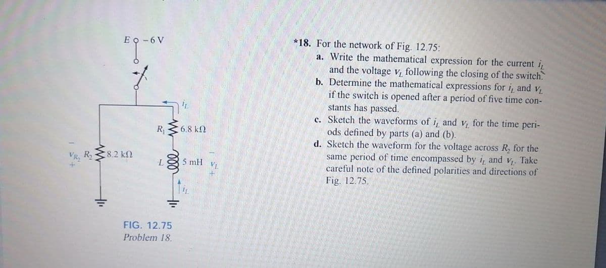
*18. For the network of Fig. 12.75:
a. Write the mathematical expression for the current i
and the voltage v₁ following the closing of the switch.
b. Determine the mathematical expressions for i, and V₁
if the switch is opened after a period of five time con-
stants has passed.
c. Sketch the waveforms of i, and v, for the time peri-
ods defined by parts (a) and (b).
d. Sketch the waveform for the voltage across R₂ for the
same period of time encompassed by i and v₁. Take
careful note of the defined polarities and directions of
Fig. 12.75.
Expert Solution
This question has been solved!
Explore an expertly crafted, step-by-step solution for a thorough understanding of key concepts.

Step by step
Solved in 3 steps

Knowledge Booster


Learn more about
Need a deep-dive on the concept behind this application? Look no further. Learn more about this topic, electrical-engineering and related others by exploring similar questions and additional content below.Recommended textbooks for you
Power System Analysis and Design (MindTap Course …
Electrical Engineering
ISBN:
9781305632134
Author:
J. Duncan Glover, Thomas Overbye, Mulukutla S. Sarma
Publisher:
Cengage Learning
Power System Analysis and Design (MindTap Course …
Electrical Engineering
ISBN:
9781305632134
Author:
J. Duncan Glover, Thomas Overbye, Mulukutla S. Sarma
Publisher:
Cengage Learning