59: For the beam in Fig. P5.9, determine the extreme value of the shearing force and bending moment at point D due to the concentrated live load of 30 kN, a unifomly distributed live load of 3 kN/m (of any length), and a uniformly distributed dead load of 1 kN/m.
59: For the beam in Fig. P5.9, determine the extreme value of the shearing force and bending moment at point D due to the concentrated live load of 30 kN, a unifomly distributed live load of 3 kN/m (of any length), and a uniformly distributed dead load of 1 kN/m.

Chapter9: Application Of Influence Lines
Section: Chapter Questions
Problem 15P

Related questions
Question
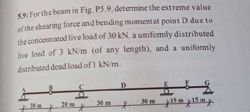
Transcribed Image Text:59. For the beam in Fig. P5.9, determine the extreme value
of the shearing force and bending moment at point D due to
the concentrated live load of 30 kN, a unifomly distributed
live load of 3 kN/m (of any length), and a uniformly
distributed dead load of 1 kN/m.
F
20 m ¥
30 m
30 m 15 m y15 m*
20 m
Expert Solution
This question has been solved!
Explore an expertly crafted, step-by-step solution for a thorough understanding of key concepts.

This is a popular solution!

Trending now
This is a popular solution!

Step by step
Solved in 5 steps with 1 images

Knowledge Booster


Learn more about
Need a deep-dive on the concept behind this application? Look no further. Learn more about this topic, civil-engineering and related others by exploring similar questions and additional content below.Recommended textbooks for you