6. A coil whose resistance is 100 ohm and inductance of L1 is connected in parallel with a series combination of inductance L2 and capacitance C. When w 1 x 10⁵, the impedance of the whole combination is 300 ohms, purely resistive. When w = 2 x 10⁵ no current flows towards the coil. Find the value of C. a. 38.23 nF b. 34.02 nF c. 35.36 nF d. 32.77 nF Task 3
6. A coil whose resistance is 100 ohm and inductance of L1 is connected in parallel with a series combination of inductance L2 and capacitance C. When w 1 x 10⁵, the impedance of the whole combination is 300 ohms, purely resistive. When w = 2 x 10⁵ no current flows towards the coil. Find the value of C. a. 38.23 nF b. 34.02 nF c. 35.36 nF d. 32.77 nF Task 3

Power System Analysis and Design (MindTap Course List)
6th Edition
ISBN:9781305632134
Author:J. Duncan Glover, Thomas Overbye, Mulukutla S. Sarma
Publisher:J. Duncan Glover, Thomas Overbye, Mulukutla S. Sarma
Chapter2: Fundamentals
Section: Chapter Questions
Problem 2.18P: Let a series RLC network be connected to a source voltage V, drawing a current I. (a) In terms of...

Related questions
Question
Transcribed Image Text:TASK 1
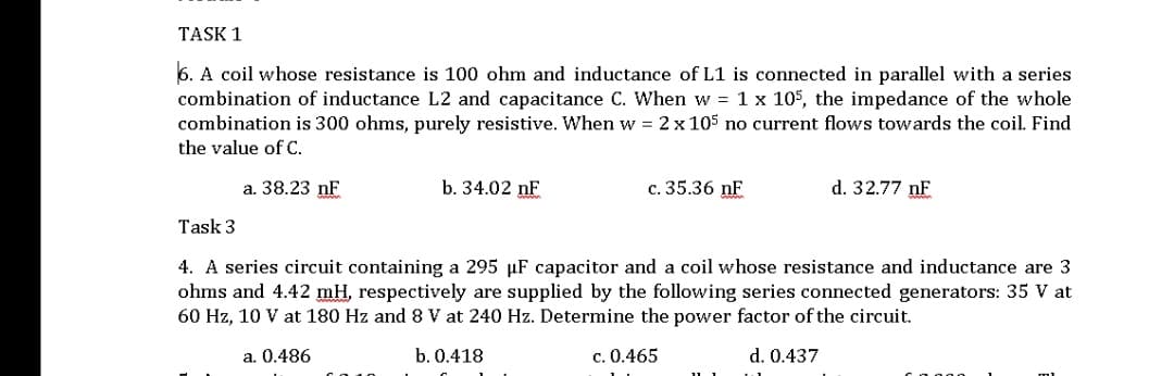
6. A coil whose resistance is 100 ohm and inductance of L1 is connected in parallel with a series
combination of inductance L2 and capacitance C. When w = 1 x 10⁵, the impedance of the whole
combination is 300 ohms, purely resistive. When w = 2 x 10⁵ no current flows towards the coil. Find
the value of C.
a. 38.23 nF
b. 34.02 nF
c. 35.36 nF
d. 32.77 nF
Task 3
4. A series circuit containing a 295 µF capacitor and a coil whose resistance and inductance are 3
ohms and 4.42 mH, respectively are supplied by the following series connected generators: 35 V at
60 Hz, 10 V at 180 Hz and 8 V at 240 Hz. Determine the power factor of the circuit.
a. 0.486
b. 0.418
c. 0.465
d. 0.437
Expert Solution
This question has been solved!
Explore an expertly crafted, step-by-step solution for a thorough understanding of key concepts.

Step by step
Solved in 3 steps with 3 images

Knowledge Booster


Learn more about
Need a deep-dive on the concept behind this application? Look no further. Learn more about this topic, electrical-engineering and related others by exploring similar questions and additional content below.Recommended textbooks for you
Power System Analysis and Design (MindTap Course …
Electrical Engineering
ISBN:
9781305632134
Author:
J. Duncan Glover, Thomas Overbye, Mulukutla S. Sarma
Publisher:
Cengage Learning
Power System Analysis and Design (MindTap Course …
Electrical Engineering
ISBN:
9781305632134
Author:
J. Duncan Glover, Thomas Overbye, Mulukutla S. Sarma
Publisher:
Cengage Learning