6.5 INFL EXAMPLE 6.15 es Draw the influence line for the force in member GB of the bridge truss ce he shown in Fig. 6-24a. FH F he H re by he 6 m FB E |D A B ad 6 m 6 m 6 m ce 6 m 0.25 ve. (a) 0.75 nd
6.5 INFL EXAMPLE 6.15 es Draw the influence line for the force in member GB of the bridge truss ce he shown in Fig. 6-24a. FH F he H re by he 6 m FB E |D A B ad 6 m 6 m 6 m ce 6 m 0.25 ve. (a) 0.75 nd

Chapter8: Influence Lines
Section: Chapter Questions
Problem 42P

Related questions
Question
Transcribed Image Text:6.5 INFL
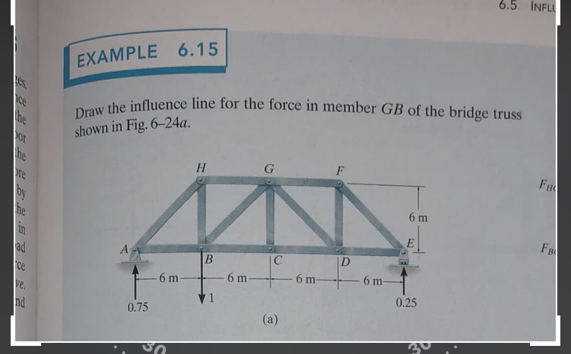
EXAMPLE 6.15
es
Draw the influence line for the force in member GB of the bridge truss
ce
he
shown in Fig. 6-24a.
FH
F
he
H
re
by
he
6 m
FB
E
|D
A
B
ad
6 m
6 m
6 m
ce
6 m
0.25
ve.
(a)
0.75
nd
Expert Solution
This question has been solved!
Explore an expertly crafted, step-by-step solution for a thorough understanding of key concepts.

This is a popular solution!

Trending now
This is a popular solution!

Step by step
Solved in 6 steps with 6 images

Recommended textbooks for you