60 A 10 Ω 5Ω www 15 Ω 6Ω 20 Ω 30 Ω www 40 Ω 60 Ω

Delmar's Standard Textbook Of Electricity
7th Edition
ISBN:9781337900348
Author:Stephen L. Herman
Publisher:Stephen L. Herman
Chapter19: Capacitors
Section: Chapter Questions
Problem 1PP: Fill in all the missing values. Refer to the formulas that follow. Resistance Capacitance Time...

Related questions
Question
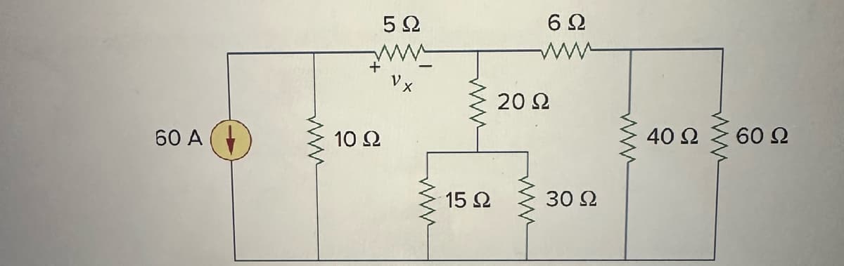
For the circuit attached, by getting equivalent resistance and then using current and/or voltage division principles, calculate vx and the power absorbed by the 60-ohm resistor.
Transcribed Image Text:60 Α
www
5Ω
www
10 Ω
15 Ω
6Ω
www
20 Ω
30 Ω
www
40 Ω
60 Ω
Expert Solution
This question has been solved!
Explore an expertly crafted, step-by-step solution for a thorough understanding of key concepts.

Step by step
Solved in 4 steps with 3 images

Recommended textbooks for you
Delmar's Standard Textbook Of Electricity
Electrical Engineering
ISBN:
9781337900348
Author:
Stephen L. Herman
Publisher:
Cengage Learning
Delmar's Standard Textbook Of Electricity
Electrical Engineering
ISBN:
9781337900348
Author:
Stephen L. Herman
Publisher:
Cengage Learning