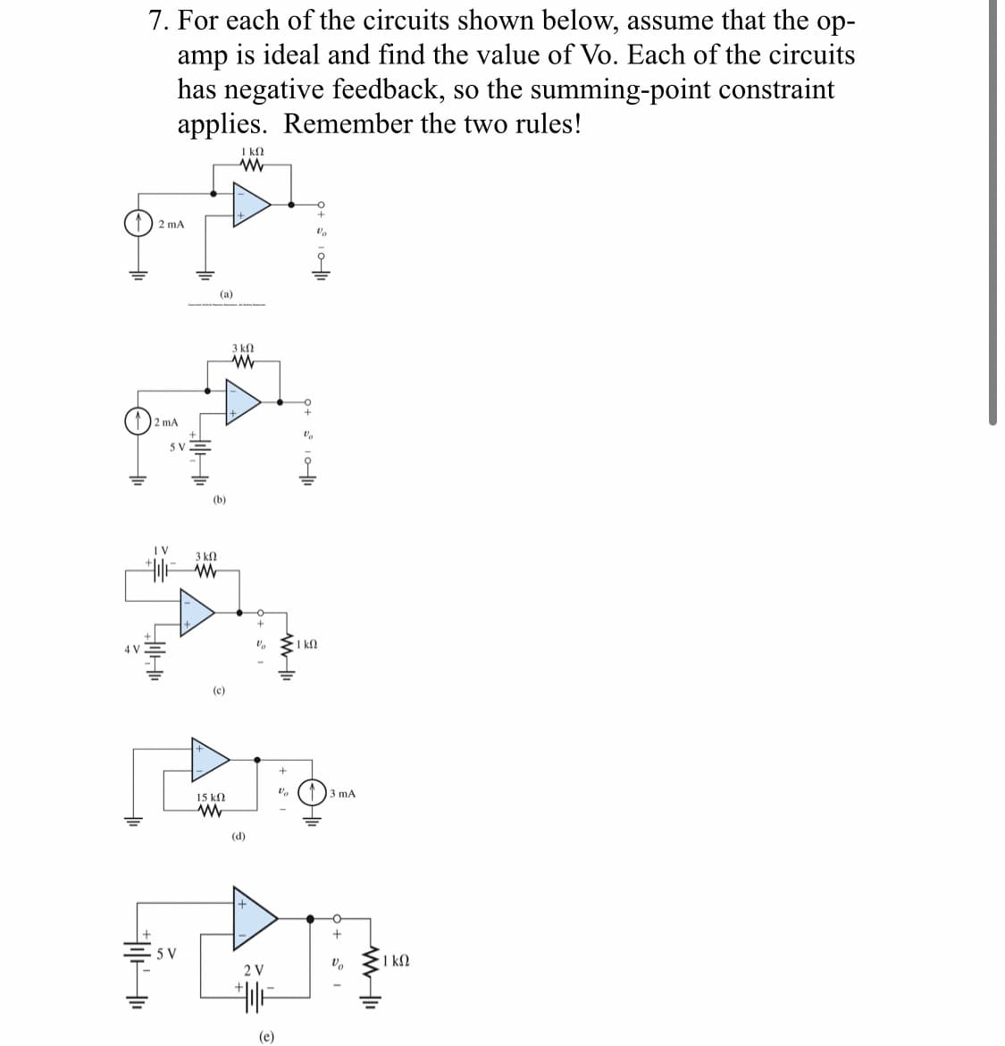
7. For each of the circuits shown below, assume that the op- amp is ideal and find the value of Vo. Each of the circuits has negative feedback, so the summing-point constraint applies. Remember the two rules! ΓΚΩ ww 2 mA 4 V 2 mA 5 V (a) (b) 1 V 3 ΚΩ W A 3 ΚΩ www (c) Vo Va · Ι ΚΩ + Va 3 mA 15 ΚΩ w (d) > 5 V 2 V ||+ (e) + 5°1 - 1 ΚΩ
Q: Y/Y G What is the function of Rs. C7 or Co in Fig. 4-5? What is the function of VR, or VR2 in Fig.…
A: Here's a breakdown of how it might work and how to solve for the output voltage (Vout):Component…
Q: AM signal input e la 1. In the diode detector circuit of Fig. 4-3, if the operational amplifier…
A: Step 1:1). In the diode detector circuit of Fig. 4-3, when the operational amplifier (µA741) is…
Q: blem... Videos Set Notation (soluti... Required documents O Sign in In Quiz - Final σ In the…
A: For an op-amp phase shift oscillator, the frequency of the circuit is given by the following…
Q: Please answer in typing format
A: Step 1:Step 2:
Q: (a) Find an expression for vo (t) fort > 0 in the circuit shown in Fig. 4 (a). 20 6 Ո 10 www www www…
A: Step 1: Step 2: Step 3: Step 4:
Q: Needs Complete solution with 100 % accuracy.
A:
Q: Communication system Let's consider a communication system where four signals with different…
A: Step 1:Step 2:
Q: with anything you can explain or do will help alot thankyou!
A: Step 1:The differentiation is done using chain rule. If u and v are functions of a variable x, then…
Q: Draw bode diagram
A: Sure, I can help you analyze the Bode diagram of the circuit. The image you sent appears to show the…
Q: Please answer in typing format
A: 4 ohm and 2 ohm are series = 6 ohm10 ohm and 6 ohm = 16 ohm6 ohm and 16 ohm are parallel =…
Q: The circuit was in steady state for a long time before the switch was closed. Please calculate V₂…
A: Step 1:Step 2:Step 3:Step 4:
Q: Calculate the magnetic flux created by the field lines uniform magnetic force of 27 passing through…
A: Thank You !
Q: The frequency of the sinusoidal voltage source in the circuit in (Figure 1) is adjusted until the…
A: Step 1:Step 2:Why the term 'obviously'?Since we are keeping w=10 which makes the imaginary term 0 at…
Q: 4. The transistor in the amplifier below has been biased such that IC - 0.3mA (no need to do DC…
A: Step 1:Step 2:Step 3:
Q: Electrical Circuits / I need a correctly hand-drawn expert solution.
A: Step 1:Step 2:Step 3:Step 4:
Q: 2.2 A vector p is 10 units long and is perpendicular to vectors q and r described here. Express the…
A: Step 1: Step 2: Step 3: Step 4:
Q: Example:a)At t=0 the switch is moved to 1 find at t=10 msec Vec,ic, Vr for the circuit b)At t=30msec…
A: I can help you understand the general approach to solving such problems and guide you through the…
Q: The circuit was in steady state for a long time before the switch was closed. Please calculate V₂…
A: Step 1: A charging capacitor connected to a voltage source acts as open circuited in steady state.…
Q: show all the workk asap
A: Step 1:Step 2:
Q: x(t) = (A+m(t)) cos(100πt) m(t) is a low-pass signal with B<<50. A=10. Write down Fourier transform…
A: Step 1: Step 2: Step 3:
Q: can u solve this in 20 min?
A: a) To derive the relation for ( Vo/Vin ) considering the non-ideal effects of the boost converter,…
Q: EXERCISE 14.3.9 (a) Find (t) fort > 0 in the circuit below. 10 V + t = 0 802 202 1/3 H io(1) ww 3/8…
A: Step 1: for t<0 for long time capacitor acts as open circuit and inductor acts as short circuit…
Q: Compute the average power delivered by the source.
A: Step 1: Since the given impedances are at 50 Hz as per the question, we need to simplify them…
Q: Please answer in typing format
A: Step 1: Step 2: Step 3: Step 4:
Q: Digital Electronics / I need the expert solution for the question handwritten.
A: However I can help you approach the problem based on some general digital electronics…
Q: Show how to find the current i4 using super meshes in mesh current analysis if i4 is -1.33 A.
A:
Q: Please answer in typing format
A: Given that,Speed of mobile station = 50m/sFrequency of transmission = 1.5GHz=1.5∗109HzDoppler spread…
Q: In the given circuit, V, 39/0°V. Find the value of Zr, that will absorb the maximum average power…
A: Step 1:Step 2:Step 3:Step 4:
Q: Please answer in typing format
A: To solve this, we'll first find the total impedance of the circuit, which is the sum of (R1) and…
Q: al In the following phase shift oscillator, what is the gain of RC network at the resonance…
A: Step 1: given in RC phase shift oscillator. f=1/(2piRC6) At resonance frequency, gain = −1/29.
Q: 480-V, 60-Hz, four-pole Y-connected induction motor runs at 1735 rpm when operating at full load.…
A: Step 1: Step 2:
Q: The below circuit is excited with an AC source with the indicated amplitude and phase. Please…
A:
Q: (a) Determine the steady-state voltage Voss (t) in the network below for t > 0 if the initial…
A: Step 1: Basic concept used • Cartesian to polar coordinate conversion: x+jy=x2+y2∠tan−1(xy) •…
Q: Answer all parts of the questions. Giving a numerical result without showing supporting work may…
A:
Q: The following loads are connected to a 3 phase 3 wire supply, 415V 50Hz supply. Between Red and…
A: a) To calculate the phase current and line current for each connected load, we'll use the formulas…
Q: Need in Detail handwritten step by step,each step
A: Step 1: Step 2: Step 3:
Q: For the starting method given in task 8, redraw each of the symbols used in the control circuit and…
A: Sure, I can help you with the control circuit symbols for the star-delta starter based on the…
Q: 2. Determine the voltages at all nodes and the currents through all branches (B=40). 3V Rc-2.2kQ Vc…
A: All the parts are solved properly with detailed explanation.Hope you got your answer. If any query…
Q: A 1200 kVA, 3.3-kV, three-phase, star-connected alternator has an effective resistance that is 1.5…
A: Step 1:Step 2:cos 41.123= 0.753 lag Step 3:
Q: 4) 10% Derive and plot the amplitude spectrum of f (t) = sin 10t. Assume the fundamental frequency…
A: Step 1:
Q: please solve a to c step by step detailed solution thank you
A:
Q: can you help find power dissipation taking die size into account. In the power dissipation formula,…
A: Yes, there is a correlation between die size and power dissipation. Generally, a smaller die size…
Q: Pls help me answer this one.
A: Here is the completed table:-| No. | Description | Value |…
Q: signal systems if periodic or not and wo fo to values
A: Step 1: Given signal x(t)=cotan(π/2-t)cotan ---> cotangent which is a trigonometric ratio. All…
Q: Videos Set Notation (soluti... Required documents Sign in C In t - Final In the following circuit…
A:
Q: Please solve a to c handwriting detailed step by step solution thank you
A: Step 1: Step 2:
Q: Q.1: Find the Fourier Transform F(w) for the following signals: f(t) -πT Π
A:
Q: Q.5: Find the Laplace Transform of the following. L[et cos 3t9t ³ +π]
A: Step 1:
Q: Solve number 1 for this example. Show all work and tips. Thank you
A: However, based on the general concepts of mesh analysis and the information you've provided, here's…
Q: Taking a transistor current gain of 250, find the value of base current needed to drive a collector…
A: To find the value of the base current needed to drive a collector current of 400 mA, we can use the…
Step by step
Solved in 2 steps
- A noninverting amplifier is built with R2 = 75 kΩ and R1 = 5.6kΩ using an op amp with an open -loop gain of 100dB, an input resistance of 500kΩ, and an output resistance of 300 Ω. What are the closed-loop gain, input resistance, and output resistance for this amplifier? (b) Repeat if the open-loop gain is changed to 94 dB.A noninverting amplifier is built with R1 = 12 kΩ and R2 = 150 kΩ using an op amp with an open-loop gain of 86 dB. What are the closed-loop gain, the gain error, and the fractional gain error for this amplifier? (b) Repeat if R1 is changed to 1.2 kΩ.A noninverting amplifier is built with R2 = 47 kΩ and R1 = 6.2k Ω using an op amp with an open-loop gain of 94 dB. What are the closed-loop gain, the gain error, and the fractional gain error for this amplifier? (b) Repeat if the open-loop gain is changed to 100 dB.
- Show the connection of a three-stage amplifier with gains of +10, -18, and -27.Use a 270-kΩ feedback resistor for all three 741 op-amp circuits. What outputvoltage will result for an input of 150 mV?Based on the simulation’s results, explain the function of a differential amplifier. (Hints: comment on the shape of Vo1 and Vo2, explain what would happen if V1 and V2 were the same, reflect on why it is important that an ideal op-amp has infinite input impedance).3A Problem 1. (P1) Three op-amps are connected in cascade configuration. An 80 microVolts signal is connected to the non-inverting input of the first op-amp. Both the 2nd and 3rd op-amps operates as inverting amplifiers. All feedback resistors are 420 KOhms while the input resistances are 71.4kOhms, 19.1kOhms, and 14KOhms respectively. 3H Determine the total gain of the circuit in Problem No. 1 (P1) a.792.105 b.9000 c.792 V d.792
- For an op-amp working in differential mode, when inputs of VI= −200 mV, andVN = +200 mV are applied, the amplifier output is recorded as Vo = 1.0012 V.When the op-amp is used in a common mode amplifier with inputs VI=VN =5V,the output is V0= 0.2217 V. Determine the common mode rejection ratio(CMRR), expressed in dB.An amplifier is formed by cascading the two operational amplifier stages as shown. What are the voltage gain, input resistance, and outputresistance for this amplifier (a) if the op amps are ideal? (b) If the op amps have an open-loop gain of 106 dB, an input resistance of 300 kΩ, and an output resistance of 200 Ω? (c) Draw the new circuit and repeat (a) and (b) if the two amplifier stages are interchanged.Find the closed-loop transconductance, input resistance, and output resistance for the series-series feedback amplifier as shown if the op amp has an open-loop gain of 80 dB, an input resistance of 25kΩ , and an output resistance of 1kΩ. Assume the amplifier is driven by a signal voltage with a 10-kΩ source resistance, and the feedback network is implemented with R2=91kΩ and R1=10kΩ.
- For the op-amp circuit shown below, find the value of vO, where R1 = 19 Ω, R2 = 14 Ω, R3 = 18 Ω, R4 = 14 Ω, Rf = 11 Ω, VS1 = 15 V, and VS2 = 3 V.An amplifier is formed by cascading the three operational amplifier stages as shown. What are the voltage gain, input resistance, and outputresistance for this amplifier (a) if the op amps are ideal? (b) If the op amps have an open-loop gain of 94 dB, an input resistance of 400 kΩ, and an output resistance of 250 Ω?An inverting amplifier is built with R1 =11kΩand R2 = 220 kΩ using an op amp with an open-loop gain of 86 dB. What are the closed-loop gain, the gain error, and fractional gain error for this amplifier? (b) Repeat if R1 is changed to 1.1 kΩ.