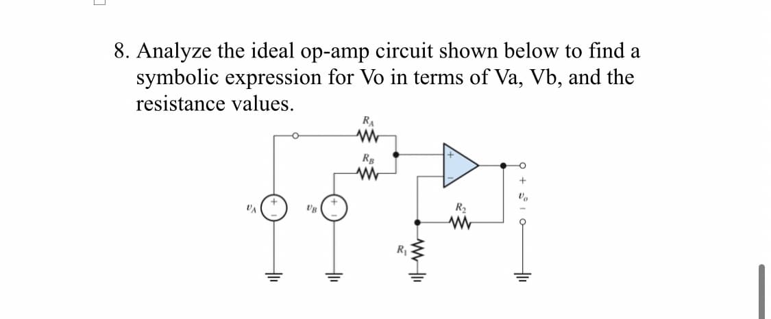
8. Analyze the ideal op-amp circuit shown below to find a symbolic expression for Vo in terms of Va, Vb, and the resistance values. RA w RB www R₂ Vo R₁ WWII www
Q: Write the types of fuses
A: so lets start by understanding what is basically a fuse?imagine you have a magical safety switch in…
Q: Solve a to c handrwitten step by step solution by also showing the inverse z transform if necessary…
A: Step 1: Step 2: Step 3: Step 4: Step 5:
Q: Q.5: Find the Laplace Transform of the following. L{te-2t - - St t sin 5t dt}
A:
Q: Using the circuit, if the current in the circuit is 15.6∠ − 30° mAp and the resistance is 560Ω, what…
A:
Q: A solenoid with 3 cm portal length a current of 400 mA. If it must produce a magnetic flux density B…
A:
Q: Please answer in typing format
A: 4 ohm and 2 ohm are series = 6 ohm10 ohm and 6 ohm = 16 ohm6 ohm and 16 ohm are parallel =…
Q: B-6-16. Consider the control system shown in Figure 2. Determine the gain K and time constant T of…
A:
Q: 어떻게 문제에 접근해야할지 모르겠어요 접근 방법과 풀이과정을 자세하게 알려주세요
A: Step 1:Step 2:Step 3:
Q: Q5 Consider a four-input CMOS NAND logic gate. Draw the circuit, then: Q6 a) Determine the W/L…
A: Certainly, I can help you design a circuit for the four-input CMOS NAND logic gate shown in the…
Q: For review purpose only no grade. please answer: Blank 1, 2, 3, 4. Thanks !
A: Step 1:
Q: For practice purpose only thanks!
A: Step 1: by mesh analysis, Apply KVL in the loop 1 as,-24+10(i1-i2)+12(i1-i3)=0by solving we get,…
Q: The below circuit is excited with an AC source with the indicated amplitude and phase. Please…
A:
Q: please solve only d with detailed step by step solution thank you
A: Step 1: Step 2:
Q: Please help with this parctice problems so I may study
A: a) To determine if the filter is Type I or Type II, we need to look at the symmetry properties of…
Q: sorry for my writing, please solve
A: Step 1: Step 2: Step 3: Step 4: Step 5: import numpy as npimport matplotlib.pyplot as plt# Define…
Q: please solve a to c detailed step by step solution thank you
A: Step 1:(a)Direct Form I structure:In the direct form I structure, the system function is implemented…
Q: Please answer in typing format
A:
Q: 3. Consider the circuit in the figure below. The circuit includes two batteries and three currents…
A: Step 1: Step 2: Step 3: Step 4:
Q: The circuit was in steady state for a long time before the switch was closed. Please calculate Vc₂…
A: Step 1:Step 2:
Q: Find the total watts, volt amperes reactive, volt amperes and power factor of the three phase…
A: Step 1:From the given circuit we can observe that1) The load is delta connected and consisting of…
Q: Pls show neat and whole solution
A: Step 1:Step 2:Step 3:
Q: please solve this question detailed step by step solution thank you
A: Step 1:
Q: Please help with these parctice problems so I may study from them
A: I can help you with the general concepts of Nyquist sampling theorem and its…
Q: Please answer in typing format
A: To solve this, we'll first find the total impedance of the circuit, which is the sum of (R1) and…
Q: Please answer in typing format
A: Inductors and capacitors are frequency dependent components.For an AC supply,The inductive…
Q: Please answer in typing format for
A: based on your description of the image being a circuit diagram, and the previous questions about…
Q: B-6-18. Consider the system shown in Figure 3. Design a compensator such that the dominant…
A: Based on the image you sent, it appears to be a circuit diagram for a voltage regulator using a…
Q: = at (5+1)3 A system with open loop transfer function as G(s) K which K system become marginal…
A:
Q: Task 2: 2. For a signal Evaluate the Fast Fourier Transform using signal flow graph. (Use Decimation…
A: Creating a signal flow graph (SFG) to evaluate the fast Fourier transform (FFT) using the decimation…
Q: Compute the average power delivered by the source.
A: Step 1: Since the given impedances are at 50 Hz as per the question, we need to simplify them…
Q: Solve for number 2. Please show all work and tips for this practice problem. Thank you
A:
Q: Name two characteristics that energy efficiency improvements have?
A: ANS:Energy efficiency improvements reduce energy consumption and save costs, making processes more…
Q: EXERCISE 14.3.9 (a) Find (t) fort > 0 in the circuit below. 10 V + t = 0 802 202 1/3 H io(1) ww 3/8…
A: Step 1: for t<0 for long time capacitor acts as open circuit and inductor acts as short circuit…
Q: Sin (X + cos x)=0.5= Find g(x), g(x)
A:
Q: Please, help show work and dont use AI pls
A: (a) Determining the value of \( K \):Given the cumulative density function (CDF) \( F_X(x) \), we…
Q: Let 10 fi(t)=5+ cos noot 50 f2(t)=1+sinn nwot a) Find the trigonometric Fourier series coefficients…
A: Step 1:Step 2:
Q: I need an expert solution in handwriting using the rules in the other picture, clear and accurate.…
A: Step 1:Step 2:
Q: The circuit in (Figure 1) is operating in the sinusoidal steady state.
A: Step 1:
Q: 480-V, 60-Hz, four-pole Y-connected induction motor runs at 1735 rpm when operating at full load.…
A: Step 1: Step 2:
Q: how do i solve this without using Laplace transform? instead solving differential equations..... if…
A:
Q: Please answer in typing format
A: Step 1: As instructed in question, after removing 50 ohms resistor and connecting 100 ohm between a…
Q: Derive and plot the amplitude spectrum of f (t) = sin 10t. Assume the fundamental frequency (00=1.
A: If you are having doubt in any step please comment here. Thank you
Q: I need an answer for this in less than 5 hours so could I please recieve an answer for this. I need…
A: Step 1:
Q: If v_1 = 5.00 V, v_2 = 1.79 V, and i_1 = -0.32 mA, how are these found using node-voltage analysis…
A:
Q: Two long, parallel wires carry currents of I₁ = 3.18 A and 12 = 4.90 A in the direction indicated in…
A: Part (a) Recall that the dot represents the current flowing out of the page. By the right-hand…
Q: Please answer in typing format
A: Step 1:Convert the given impedance to per unit values using the formula Zpu=Z×(BASEKV)2BASEMVA…
Q: the label value of the 3-phase asynchronous motor is 380 V, 4A, 50 hz, power factor 0.8, 1.5kW, 950…
A:
Q: 24 V 4 102 1292 www www I. 12 24S2 402 www Figure (3). 41 Use mesh analysis to find the current in…
A:
Q: Please answer in typing format for
A: Step 1: Step 2: Step 3: Step 4:
Q: quetion 5
A: Step 1:Step 2:Step 3:Step 4:
Trending now
This is a popular solution!
Step by step
Solved in 2 steps with 2 images
- Given circuit, assume op-amp is ideal. What is the input resistance of the circuit, RIN? What are the currents in the inputs of op-amp? i-=? i+=? What is the output resistance of the circuit, ROUT=? Find voltage VA and VB? What is the nodal equation (KCL) at node VB? Solve for VOUT=?For the OpAmp circuit shown below, give the expression for the gain, G = Vo/ViDerive the transfer function for the non-inverting op-amp shown below. Use Step-by-Step in depth explanation and answer. Please
- Design an op-amp circuit to yield the relationship shown in each equation. Vo = 8A + 8B – 3C – 12Da.) Rmin = 9KΩb.) Rin = 9KΩDesign an op-amp circuit which produce an output voltage as shown with input voltageVin= sin(wt)3) Load for a circuit with direct current source voltage The waveform of the voltage generated on it is below shown. Source for this working circuit that is symmetrical The value of the voltage and load resistance is 100 V and 5Ω respectively.It is given as. Find what is required below. d) Find the effective value of the output voltage e) Total harmonic distortion in output voltageCalculate (THD)
- An ideal op-amp circuit is shown above, with dc supply Vcc = -Vcc = 12V. Assume that vs = 3V, R1 = 2Ω, Rf = 4Ω. Please find the output voltage vo in volts.For the op-amp circuit shown below, find the value of vO, where R1 = 19 Ω, R2 = 14 Ω, R3 = 18 Ω, R4 = 14 Ω, Rf = 11 Ω, VS1 = 15 V, and VS2 = 3 V.a) Design a non-inverting amplifier using an ideal op amp that has a gain 7.5.b) If you wish to amplify signals between -2V and 1.2V using the circuit you designed in part (a) what arethe smallest power supply voltages you can use?c) Draw your final circuit diagram.d) Assume that the voltage signal source is vs = −1V and the feedback resistor Rf is replaced with avariable resistor. Specify the range of Rf (in kΩ ) which will cause the op amp to saturate?
- Which of the following is the Vo(s)/Vi(s) transfer function of the subtavernop-amp circuit? (You considered the op-amp ideal.)A single-pole op amp has an open-loop gain of 100 dB and a unity-gain frequency of 3 MHz. Find an expression for the transfer function of the integrator shown if R = 10 kΩ and C = 0.05μF. What is the integrator’s phase margin?Given the circuit below, please solve for the ff: a. What is the configuration of the given amplifier circuit below?b. How are the coupling capacitors treated in the figure at AC?Please show your clean and complete solution