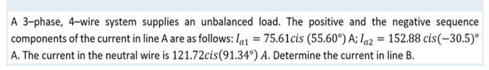
A 3-phase, 4-wire system supplies an unbalanced load. The positive and the negative sequence components of the current in line A are as follows: Ia1 = 75.61cis (55.60°) A; la2 = 152.88 cis(-30.5)° A. The current in the neutral wire is 121.72cis (91.34°) A. Determine the current in line B.
Q: if v1=8cos(377t+30) and v2 leads v1 by 20 degrees and is greater in magintude by factor of 4 what is…
A: Given data, V1=8cos377t+300 V2 leads V1 by 200 and magnitude is greater by 4 times. Time t=150 ms =…
Q: A three-phase induction motor is taking 40 kW, the slip being 4%, stator losses amount to 800 watts,…
A:
Q: A lossless transmission line having 50 Ω characteristic impedance and length λ/4 is short-circuited…
A:
Q: a) An operational amplifier with non-inverting voltage feedback is given in Figure Q4.a. It has the…
A:
Q: A lossless transmission line having 50 Ω characteristic impedance and length λ/4 is short-circuited…
A: We know that the input impedance for a loss less transmission line for a quater wave λ4 is given…
Q: ) Two feedback configurations are shown in Figures Q1.a(i) and Q1.a(ii). Derive the closed-loop gain…
A: Here Given two figures having feedback.
Q: Eq5. A 4-pole, 3-phase induction motor operates from a supply whose frequency is 50 Hz. Calculate:…
A: Given: A 3-phase induction motor with P=4f=50 Hz
Q: Briefly explain what you mean by discrete system and continuous system.
A:
Q: Ex: For the circuit in fig - by using mesh analysis Find 1- The Power dissiped in resistance (32) 2-…
A:
Q: Referring to Figure below: (Assume values of VBE = VCE(sat) = 0.7 for both device) Given: Vin = 45…
A: The circuit is given as'VG=VCEsat=0.7V Now the voltage across the gate terminal will be…
Q: Given the vector field H = xy²zax + x²yzay + xyz²ą, express it in cylindrical system at point (3,…
A: It is given that: H=xy2zax+x2yzay+xyz2azpoints3,-4,5
Q: AM wave may be represented as E(t) cos oct where E(t) is a. Envelope of the AM wave b. Carrier…
A:
Q: What is the difference between standard FSK and MSK? What is the advantage of MSK?
A: Solution !! Minimum Shift Keying (MSK): The minimum frequency space that allows 2 fsks representing…
Q: Consider the following circuit shown in below figure. If Vo R; = 1 kΩ www E₁ = 5V V₂ + +V -V V₂ =…
A: Given circuit: Output voltage, Vo=10.3 V
Q: Find the Thevenin equivalent with respect to the terminals a,b and determine the current across 1.5…
A: Given:
Q: A shunt resistance of 100 Ω is used with the galvanometer having internal resistance of 1000 Ω.…
A:
Q: 1. True or false: In direct current (DC), the electric charge (current) only flows in one direction.…
A:
Q: The electric potential of some configuration is given by the expression V (r)= A– where A and å are…
A: The electric potential is given as: Vr=Ae-λrr The electric field is derived from the electric…
Q: Analog signal may be converted into digital signal by
A: The correct option along with the explanation is provided in the following section.
Q: 7. Given the following transfer function: 6s²+66s+60 100s²+20s+1 H(s) = With an input of x(t) =…
A:
Q: In a torsion head type electrodynamometer a current of 25 A requires a deflection of 90° in the head…
A: We have been given an electrodynamometer with, I = 25 and θ = 90° and We have been asked to find,…
Q: A 0.250 H inductor is joined in series with a 10 µF capacitor. Find the supply frequency in order…
A: Given that: Inductor and capacitor are connected in series. L=0.250HC=10 μF Find supply frequency…
Q: 1. Using the least square estimation, find the parameters w, and w, for y=w₂x₂ +w₂x₂ to map the…
A:
Q: image
A: The circuit is shown below: In the above circuit at node a, I3=I1+I2................(1) Applying…
Q: A Write the Boolean expression of the following Logic diagram. BC D= C' 11
A: Given data, Logic diagram
Q: A load is plugged into a normal 230V power outlet. The power is 1.5 kW, and the power angle is 35⁰.…
A:
Q: An ac supply of 220 V is applied to a half-wave rectifier circuit through transformer with a turns…
A:
Q: Hartley oscillator is commonly used in 1. Radio receivers 2. Radio transmitters 3. TV receivers 4.…
A: The correct option along with the explanation is provided in the following section.
Q: Find the voltage across 20 resistor due to 20V source 20 W 20V 10
A: Given circuit,
Q: 3) Power of a 100W, 110 V lamp is to be varied by controlling the firing angle of an SCR in a…
A: Given: Vrms=110 V, P=100 W, firing angle α=60° Required: RMS voltage and current measured in the…
Q: 1. True or false: In direct current (DC), the electric charge (current) only flows in one direction.…
A: DC current : DC current also known as direct current this current flows only in one direction since…
Q: 1. Discuss the functions and application of at least 3 protective relays that are being used in 13.2…
A: The protective relays in an Electrical distribution system are used for preventive management of…
Q: Plot the capacitor voltage
A:
Q: 3-) Three-phase, 100 km long unit length and serial impedance per phase is 0,125+j0.34 2/km. The…
A:
Q: Find currents 11,12, and 13 in the circuit.
A: The current through the mesh can be calculated by using the mesh analysis after applying dot…
Q: What is the total power in a circuit in which the non-sinusoidal equations of the voltage and…
A:
Q: 4. Pedro walks at the speed of 40 meters/min from the school to home, by taking the longer route of…
A: Given Speed: 40meters/min Longer route is: 100 meters to north and then 100 meters to east. Mother…
Q: 1) Draw the compete circuit with the op-amp included. 2) Obtain equations for the contribution made…
A: According to the question, we need to solve the given circuit of the OP-AMP.
Q: What is the maximum transmission efficiency of an AM signal?
A: The correct option along with the explanation has been provided in the following section.
Q: For the signal x(n) = 7(1/3)^n u(n)-6(1/2)^n u(n), find the z-transform and ROC
A:
Q: EAD= 208 V 20 ECA = 208 V / 120° 000 W₁ Enc208 V-120 W₂ voo ell Ice 1202 ww 150 120 100 000 2002
A:
Q: To which, current and resistance are directly proportional? a. Voltage b. Power c. Current d.…
A: In these questions, We need to choose the correct options We are solving this questions using the…
Q: If an AC signal has a peak voltage of 55V, what is the average value voltage? a. 110 V b. 17.5070 V…
A:
Q: The OUTPUT logic, as you know, depends on the current state. Q1 Q2 0 0 CD O t 6 1 ( oe 0 [ 8 Qo 0 1…
A: Given: Truth table for the problem. We have to determine the logic expressions for various variables…
Q: 1.25 Assuming the diodes to be ideal in the figure, for the output to be clipped, the input voltage…
A: When , 2V > VAB > -1V Then D1 and D2 will be ON and Vo = – 2 volt. For D1 to be OFF, VAB <…
Q: A single-phase motor is rated 5HP, 75% pf and 220V. What is the approximate size of capacitor needed…
A:
Q: 1.21 The i-v characteristics of the diode in the circuit given below are: i = v-0.7 -A, v20.7V 500 O…
A:
Q: Find the phasor domain of v(t) = 120 cos(wt + 50°) V and i(t) = 5 sin (wt - 15°) A
A: Given: vt=120cosωt+50° V and it=5sinωt-15° A
Q: Que 2.23. What should be the value of R, so the maximum po can be transferred from the source to R,…
A: In this question, We need to determine the value of load resistance RL as shown the circuit for…
Q: Consider a causal second-order system with the transfer function 1 G(s) = 1+2s+s² with a unit-step…
A:
Solve the given problem
Step by step
Solved in 3 steps with 3 images
- A 60-Hz, single-phase two-wire overhead line has solid cylindrical copper conductors with a 1.5 cm diameter. The conductors are arranged in a horizontal configuration with 0.5 m spacing. Calculate in mH/km (a) the inductance of each conductor due to internal flux linkages only, (b) the inductance of each conductor due to both internal and external flux linkages, and (c) the total inductance of the line.Determine the bus admittance matrix (Ybus) for the three-phase power system shown in Figure 6.23 with input data given in Table 6.11 and partial results in Table 6.12. Assume a three-phase 100 MVA per unit base. TABLE 6.11 Bus input data for Problem 6.20 TABLE 6.12 Partially Completed Bus Admittance Matrix (Ybus) for Problem 6.30A balanced three-phase load is connected to a 4.16-kV, three-phase, fourwire, grounded-wye dedicated distribution feeder. The load can be mode led by an impedance of ZL=(4.7+j9)/phase, wye-connected. The impedance of the phase conductors is (0.3+j1). Determine the following by using the phase A to neutral voltage as a reference and assume positive phase sequence: (a) Line currents for phases A, B, and C. (b) Line-to-neutral voltages for all three phases at the load. (c) Apparent. active, and reactive power dissipated per phase, and for all three phases in the load. (d) Active power losses per phase and for all three phases in the phase conductors.
- PowerWorid Simulator case Problem 3_60 duplicates Example 3.13 except that a resistance term of 0.06 per unit has been added to the transformer and 0.05 per unit to the transmission line. Since the system is no longer lossless, a field showing the real power losses has also been added to the oneline. With the LTC tap fixed at 1.05, plot the real power losses as the phase shift angle is varied from 10 to +10 degrees. What value of phase shift minimizes the system losses?In a 3-phase, 4-wire system, the currents in R, Y and B lines under abnormal conditions of loading are as under : IR = 100 ∠30º A ; IY = 50 ∠300º A ; IB = 30 ∠180º A. Calculate the positive, negative and zero sequence currents in the R-line and current in the neutral wire.What load can be delivered by a 3-phase overhead line 5 km long with a pressure drop of 10%. Given that the station voltage is 11 kV, resistance per km of each line 0.09 Ω, reactance per km 0.08 Ω and the power factor of the load 0.8 lagging. ..
- A 3-phase overhead transmission line delivers a load of 80 MW at0.8 p.f. lagging and 220 kV between the lines. Its total seriesimpedance per phase and total shunt admittance per phase are 200ohms with an angle of 80 degrees and 0.0013 mho with an angle of90 degrees per phase respectively. Using nominal-T method,determine the following:(i) A, B, C, D constants of the line(ii) Sending end voltage(iii) Sending end current(iv) Sending end power factor(v) Transmission efficiency of the lineAn 11 KV, 3-phase transmission line has a resistance of 1.5 Ω and reactance of 4 Ω per phase.Calculate the percentage regulation and efficiency of the line when a total load of 5000 KVA at 0.8 lagging power factor is applied at 11KV at the distant end.Suppose a completely transposed 60-Hz three-phase line has flat horizontal phase spacing with 10 m between adjacent conductors. The conductors are 1,590,000 cmil ACSR with 54/3 stranding. Line length is 200 km. Assume the line voltage is 345 kV, at 60 Hz. i) Calculate the inductance in H/m. ii) The inductive reactance in ohm/m.
- A single-line diagram of a three-phase balanced system is given below. A bolted threephase short circuit occurs at point P, when the operating voltage was 21 kV there. Calculate the rated interrupting current rating of circuit breaker A, D and E, both in per unit and Ampere value. Answer follow image.A three-phase transposed line is composed of one ACSR 1,431,000 cmil, 47/7 Bobolink conductor per phase with flat horizontal spacing of 11 meters as shown in Figure (a). The conductors have a diameter of 3.625 cm and a GMR of 1.439 cm. The line is to be replaced by a three-conductor bundle of ACSR 477,000 cmil, 26/7 Hawk conductors having the same cross-sectional area of aluminum as the single-conductor line (Figure (b)). The conductors have a diameter of 2.1793 cm and a GMR of 0.8839 cm. The new line will also have a flat horizontal configuration, but it is to be operated at a higher voltage and therefore the phase spacing is increased to 14 m as measured from the center of the bundles as shown in Figure (b). The spacing between the conductors in the bundle is 45 cm. Determine the inductance and capacitance for both lines. Calculate the percentage change in the capacitance and inductance for both lines. Interpret these changes.A three-phase transposed line is composed of one ACSR Bobolink conductor per phase with a horizontal spacing of 11 meters as shown in the figure. phase with a horizontal spacing of 11 meters as shown in the figure. The conductors have a diameter of 3.625 cm and a RMG of 1.439 cm. Calculate the inductance and capacitance to the neutral of the line.