circuit is constructed

Delmar's Standard Textbook Of Electricity
7th Edition
ISBN:9781337900348
Author:Stephen L. Herman
Publisher:Stephen L. Herman
Chapter17: Resistive-inductive Series Circuits
Section: Chapter Questions
Problem 2PA: You are a journeyman electrician working in an industrial plant. Your task is to connect an inductor...

Related questions

Concept explainers
KVL and KCL
KVL stands for Kirchhoff voltage law. KVL states that the total voltage drops around the loop in any closed electric circuit is equal to the sum of total voltage drop in the same closed loop.
Sign Convention
Science and technology incorporate some ideas and techniques of their own to understand a system skilfully and easily. These techniques are called conventions. For example: Sign conventions of mirrors are used to understand the phenomenon of reflection and refraction in an easier way.
Question
6
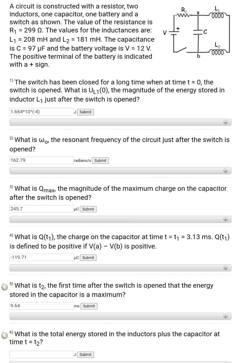
Transcribed Image Text:A circuit is constructed with a resistor, two
inductors, one capacitor, one battery and a
switch as shown. The value of the resistance is
R1 = 299 Q. The values for the inductances are:
V
L1 = 208 mH and L2 = 181 mH. The capacitance
is C = 97 µF and the battery voltage is V = 12 V.
The positive terminal of the battery is indicated
with a + sign.
L2
b
1) The switch has been closed for a long time when at timet = 0, the
switch is opened. What is UL1(0), the magnitude of the energy stored in
inductor L1 just after the switch is opened?
1.664*10^(-4)
Submit
+)
2)
What is wo, the resonant frequency of the circuit just after the switch is
opened?
162.79
radians/s Submit
3)
'What is Qmax, the magnitude of the maximum charge on the capacitor
after the switch is opened?
245.7
uc Submit
4)
What is Q(tj), the charge on the capacitor at time t = t1 = 3.13 ms. Q(tj)
is defined to be positive if V(a) – V(b) is positive.
|-119.71
µC Submit
5) What is t2, the first time after the switch is opened that the energy
stored in the capacitor is a maximum?
9.64
ms Submit
6) What is the total energy stored in the inductors plus the capacitor at
time t = t2?
J Submit
Expert Solution
This question has been solved!
Explore an expertly crafted, step-by-step solution for a thorough understanding of key concepts.

Step by step
Solved in 2 steps

Knowledge Booster


Learn more about
Need a deep-dive on the concept behind this application? Look no further. Learn more about this topic, electrical-engineering and related others by exploring similar questions and additional content below.Recommended textbooks for you
Delmar's Standard Textbook Of Electricity
Electrical Engineering
ISBN:
9781337900348
Author:
Stephen L. Herman
Publisher:
Cengage Learning
Delmar's Standard Textbook Of Electricity
Electrical Engineering
ISBN:
9781337900348
Author:
Stephen L. Herman
Publisher:
Cengage Learning