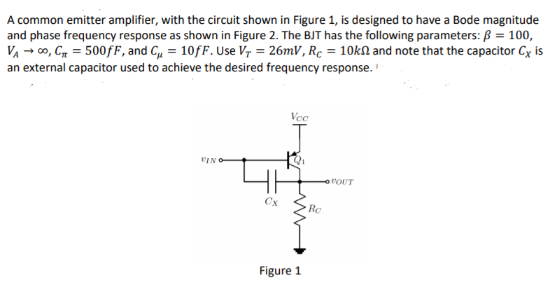
A common emitter amplifier, with the circuit shown in Figure 1, is designed to have a Bode magnitude and phase frequency response as shown in Figure 2. The BJT has the following parameters: B = 100, VA → co, C = 500fF, and Cu = 10fF. Use Vr = 26mV, Rc = 10KN and note that the capacitor Cx is an external capacitor used to achieve the desired frequency response.
A common emitter amplifier, with the circuit shown in Figure 1, is designed to have a Bode magnitude and phase frequency response as shown in Figure 2. The BJT has the following parameters: B = 100, VA → co, C = 500fF, and Cu = 10fF. Use Vr = 26mV, Rc = 10KN and note that the capacitor Cx is an external capacitor used to achieve the desired frequency response.

Introductory Circuit Analysis (13th Edition)
13th Edition
ISBN:9780133923605
Author:Robert L. Boylestad
Publisher:Robert L. Boylestad
Chapter1: Introduction
Section: Chapter Questions
Problem 1P: Visit your local library (at school or home) and describe the extent to which it provides literature...

Related questions
Question
![70
195
180
60
165
150
50
135
120
40
105
90
30
75
60
20
45
10
30
15
1.E+05
1.E+06 1.E+07 1.E+08 1.E+09 1.E+10 1.E+11 1.E+12 1.E+13
1.E+05
1.E+06 1.E+07 1.E+08 1.E+09 1.E+10 1.E+11 1.E+12 1.E+13
Frequency, rad/sec
Frequency, rad/sec
Figure 2
Write the generalized form of the amplifier's transfer function,
Vout (w).
a.
A(w):
Vin
Determine the value of the capacitor Cx.
What should be the quiescent collector current of the transistor?
b.
C.
|A{»}], dB
LA(o), degrees](/v2/_next/image?url=https%3A%2F%2Fcontent.bartleby.com%2Fqna-images%2Fquestion%2F07178837-0710-4e34-8d95-54592156303e%2F1dbe6eec-cd3d-468a-a72b-dcfaca5e47be%2Flumti1s_processed.png&w=3840&q=75)
Transcribed Image Text:70
195
180
60
165
150
50
135
120
40
105
90
30
75
60
20
45
10
30
15
1.E+05
1.E+06 1.E+07 1.E+08 1.E+09 1.E+10 1.E+11 1.E+12 1.E+13
1.E+05
1.E+06 1.E+07 1.E+08 1.E+09 1.E+10 1.E+11 1.E+12 1.E+13
Frequency, rad/sec
Frequency, rad/sec
Figure 2
Write the generalized form of the amplifier's transfer function,
Vout (w).
a.
A(w):
Vin
Determine the value of the capacitor Cx.
What should be the quiescent collector current of the transistor?
b.
C.
|A{»}], dB
LA(o), degrees
Transcribed Image Text:A common emitter amplifier, with the circuit shown in Figure 1, is designed to have a Bode magnitude
and phase frequency response as shown in Figure 2. The BJT has the following parameters: B = 100,
VA → 00, C = 500fF, and C = 10fF. Use Vr = 26mV, Rc = 10kN and note that the capacitor Cx is
an external capacitor used to achieve the desired frequency response.
Vcc
VIN O
VOUT
Cx
Rc
Figure 1
Expert Solution
This question has been solved!
Explore an expertly crafted, step-by-step solution for a thorough understanding of key concepts.

Step by step
Solved in 4 steps with 9 images

Knowledge Booster


Learn more about
Need a deep-dive on the concept behind this application? Look no further. Learn more about this topic, electrical-engineering and related others by exploring similar questions and additional content below.Recommended textbooks for you
Introductory Circuit Analysis (13th Edition)
Electrical Engineering
ISBN:
9780133923605
Author:
Robert L. Boylestad
Publisher:
PEARSON

Delmar's Standard Textbook Of Electricity
Electrical Engineering
ISBN:
9781337900348
Author:
Stephen L. Herman
Publisher:
Cengage Learning

Programmable Logic Controllers
Electrical Engineering
ISBN:
9780073373843
Author:
Frank D. Petruzella
Publisher:
McGraw-Hill Education
Introductory Circuit Analysis (13th Edition)
Electrical Engineering
ISBN:
9780133923605
Author:
Robert L. Boylestad
Publisher:
PEARSON
Delmar's Standard Textbook Of Electricity
Electrical Engineering
ISBN:
9781337900348
Author:
Stephen L. Herman
Publisher:
Cengage Learning
Programmable Logic Controllers
Electrical Engineering
ISBN:
9780073373843
Author:
Frank D. Petruzella
Publisher:
McGraw-Hill Education

Fundamentals of Electric Circuits
Electrical Engineering
ISBN:
9780078028229
Author:
Charles K Alexander, Matthew Sadiku
Publisher:
McGraw-Hill Education

Electric Circuits. (11th Edition)
Electrical Engineering
ISBN:
9780134746968
Author:
James W. Nilsson, Susan Riedel
Publisher:
PEARSON

Engineering Electromagnetics
Electrical Engineering
ISBN:
9780078028151
Author:
Hayt, William H. (william Hart), Jr, BUCK, John A.
Publisher:
Mcgraw-hill Education,