(a) Determine current I in the circuit below. 10Ω 40 Ω 30 Ω 60 Ω 352 +1 5Ω 25 Ω 50 V 10 Ω 10 Ω
(a) Determine current I in the circuit below. 10Ω 40 Ω 30 Ω 60 Ω 352 +1 5Ω 25 Ω 50 V 10 Ω 10 Ω

Delmar's Standard Textbook Of Electricity
7th Edition
ISBN:9781337900348
Author:Stephen L. Herman
Publisher:Stephen L. Herman
Chapter18: Resistive-inductive Parallel Circuits
Section: Chapter Questions
Problem 13PP: In an R-L parallel circuit, IT=1.25 amps, R=1.2k, and XL=1k. Find IR

Related questions
Question
Transcribed Image Text:Exercise 4.1.24
EXERCISE 4.1.24
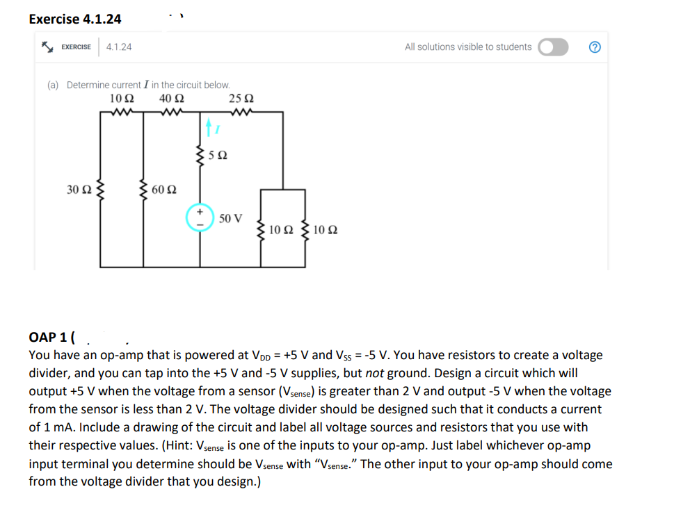
(a) Determine current I in the circuit below.
1092
40 Ω
30 ΩΣ
3 60 Ω
€592
2592
50 V
10 2210 22
All solutions visible to students
?
OAP 1 (.
You have an op-amp that is powered at VDD = +5 V and VSS = -5 V. You have resistors to create a voltage
divider, and you can tap into the +5 V and -5 V supplies, but not ground. Design a circuit which will
output +5 V when the voltage from a sensor (Vsense) is greater than 2 V and output -5 V when the voltage
from the sensor is less than 2 V. The voltage divider should be designed such that it conducts a current
of 1 mA. Include a drawing of the circuit and label all voltage sources and resistors that you use with
their respective values. (Hint: Vsense is one of the inputs to your op-amp. Just label whichever op-amp
input terminal you determine should be Vsense with "Vsense." The other input to your op-amp should come
from the voltage divider that you design.)
Expert Solution
This question has been solved!
Explore an expertly crafted, step-by-step solution for a thorough understanding of key concepts.

This is a popular solution!

Trending now
This is a popular solution!

Step by step
Solved in 2 steps with 2 images

Knowledge Booster


Learn more about
Need a deep-dive on the concept behind this application? Look no further. Learn more about this topic, electrical-engineering and related others by exploring similar questions and additional content below.Recommended textbooks for you
Delmar's Standard Textbook Of Electricity
Electrical Engineering
ISBN:
9781337900348
Author:
Stephen L. Herman
Publisher:
Cengage Learning
Delmar's Standard Textbook Of Electricity
Electrical Engineering
ISBN:
9781337900348
Author:
Stephen L. Herman
Publisher:
Cengage Learning