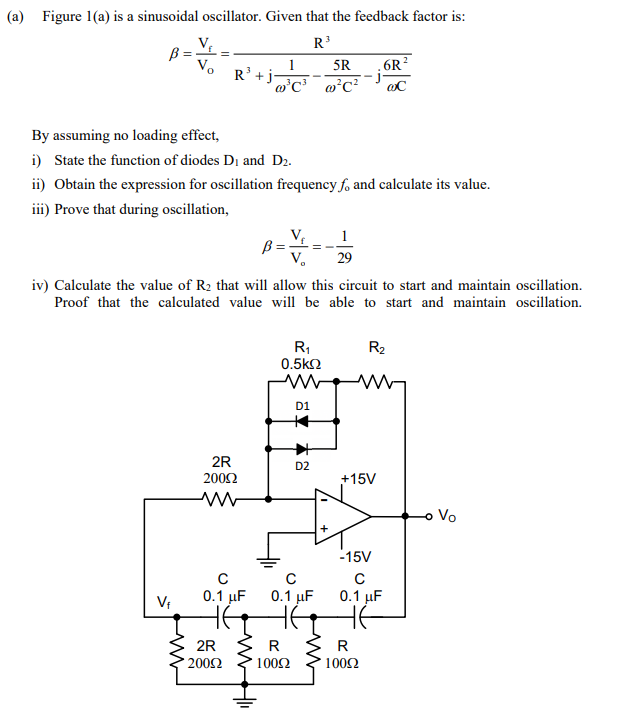
(a) Figure 1(a) is a sinusoidal oscillator. Given that the feedback factor is: R³ B= 1 5R R³+j²C²²C² .6R2 CC By assuming no loading effect, i) State the function of diodes D₁ and D₂. ii) Obtain the expression for oscillation frequency fo and calculate its value. iii) Prove that during oscillation, B = V1 = -7 29
(a) Figure 1(a) is a sinusoidal oscillator. Given that the feedback factor is: R³ B= 1 5R R³+j²C²²C² .6R2 CC By assuming no loading effect, i) State the function of diodes D₁ and D₂. ii) Obtain the expression for oscillation frequency fo and calculate its value. iii) Prove that during oscillation, B = V1 = -7 29

Introductory Circuit Analysis (13th Edition)
13th Edition
ISBN:9780133923605
Author:Robert L. Boylestad
Publisher:Robert L. Boylestad
Chapter1: Introduction
Section: Chapter Questions
Problem 1P: Visit your local library (at school or home) and describe the extent to which it provides literature...

Related questions
Question
Transcribed Image Text:(a) Figure 1(a) is a sinusoidal oscillator. Given that the feedback factor is:
R³
B ===
V₂
By assuming no loading effect,
i) State the function of diodes D₁ and D2.
ii) Obtain the expression for oscillation frequency f, and calculate its value.
iii) Prove that during oscillation,
V₁
R³+j-
1 5R .6R²
@³C³ w²C² @C
iv) Calculate the value of R₂ that will allow this circuit to start and maintain oscillation.
Proof that the calculated value will be able to start and maintain oscillation.
2R
200Ω
с
0.1 μF
2R
200Ω
B =
V₂
R₁
0.5ΚΩ
D1
+4
R
10092
D2
с
0.1 μF
HE
R₂
+15V
-15V
с
0.1 μF
R
10092
- Vo
Expert Solution
This question has been solved!
Explore an expertly crafted, step-by-step solution for a thorough understanding of key concepts.

Step by step
Solved in 5 steps with 2 images

Knowledge Booster


Learn more about
Need a deep-dive on the concept behind this application? Look no further. Learn more about this topic, electrical-engineering and related others by exploring similar questions and additional content below.Recommended textbooks for you
Introductory Circuit Analysis (13th Edition)
Electrical Engineering
ISBN:
9780133923605
Author:
Robert L. Boylestad
Publisher:
PEARSON

Delmar's Standard Textbook Of Electricity
Electrical Engineering
ISBN:
9781337900348
Author:
Stephen L. Herman
Publisher:
Cengage Learning

Programmable Logic Controllers
Electrical Engineering
ISBN:
9780073373843
Author:
Frank D. Petruzella
Publisher:
McGraw-Hill Education
Introductory Circuit Analysis (13th Edition)
Electrical Engineering
ISBN:
9780133923605
Author:
Robert L. Boylestad
Publisher:
PEARSON
Delmar's Standard Textbook Of Electricity
Electrical Engineering
ISBN:
9781337900348
Author:
Stephen L. Herman
Publisher:
Cengage Learning
Programmable Logic Controllers
Electrical Engineering
ISBN:
9780073373843
Author:
Frank D. Petruzella
Publisher:
McGraw-Hill Education

Fundamentals of Electric Circuits
Electrical Engineering
ISBN:
9780078028229
Author:
Charles K Alexander, Matthew Sadiku
Publisher:
McGraw-Hill Education

Electric Circuits. (11th Edition)
Electrical Engineering
ISBN:
9780134746968
Author:
James W. Nilsson, Susan Riedel
Publisher:
PEARSON

Engineering Electromagnetics
Electrical Engineering
ISBN:
9780078028151
Author:
Hayt, William H. (william Hart), Jr, BUCK, John A.
Publisher:
Mcgraw-hill Education,