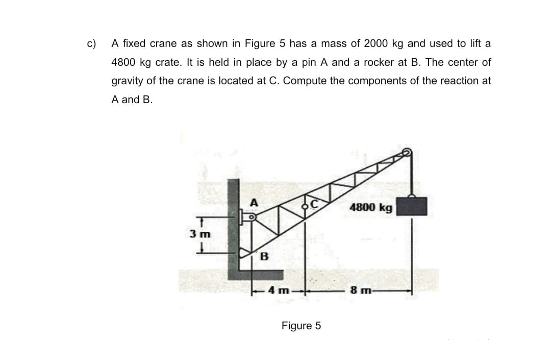
A fixed crane as shown in Figure 5 has a mass of 2000 kg and used to lift a 4800 kg crate. It is held in place by a pin A and a rocker at B. The center of gravity of the crane is located at C. Compute the components of the reaction at A and B. 4800 kg 3 m 4 m 8 m Figure 5
Q: Figure (2) shows a lift truck in a warehouse that handles 20 bags of concrete each having a mass of…
A: Draw the free body diagram for the above problem.
Q: Q 4: The jib crane is fixed at ( A ) and carry a box of ( 2500 kg ) mass, as shown in the figure.…
A:
Q: Three cylinders are piled in a rectangular ditch as shown in figure. Determine the reaction between…
A: Draw the free-body diagram of each cylinder.
Q: 8. If you stand on one foot while holding your other leg up behind you, your muscles apply a force…
A: Given data: Mass of lower leg, m = 4 kg. Calculate the weight of the leg, W=mg=4 kg×9.81 m/s2×1 N1…
Q: A simplified crane is shown in Figure 9 lifting a 400-kg load. The crane is supported by a pin joint…
A: given load weight = 400 kg crane is supported at A with a pin joint, so applying equilibrium…
Q: The figure below shows the hollow cylinder that each weighs 100 lb.
A:
Q: Problem. The frame shown in the figure is supported in pivots at A and B. Each member weighs 5 kN/m.…
A: Given;-Each member weight= 5 kN/mAC=1.5mCF=3mFB=1.5mCD=4mDE=2mForce at E downwards=380 kNTo…
Q: Forces of 5 Nare applied to the handles of the pa- Determine the force exerted per punch shown in…
A: Consider the free body diagram of the single lever as shown below. Here,
Q: The Dumpster D of the truck, which has a weight of 4,200 lb and a center of gravity at G is…
A: Given :- weight of the truce , w = 42 00 Lb
Q: Calculate the support reactions at A and B for the loaded beam. 96 lb/ft B 2.1 5.7' 74 lb
A: Convert the uniformly varying load into point load, F=12×5.7 ft×96 lb/ft=273.6 lb Calculate the…
Q: A container of mass m = 120 kg is supported by three cables as shown.
A: Draw a Free-body diagram of Container, Vector AB is represented as, Unit vector of AB is…
Q: In the figure below, a diver who weighs 65kg stands at one end of a diving board preparing for a…
A: Given Data: Mass of diver, md=65 kg Mass of board, mb=20 kg
Q: The horizontal reaction at support O will be at the 100 lb 1 ft 50 lb 3 ft 3 -3 ft 150 lb O non of…
A:
Q: 2: Calculate the largest mass that can hang in this system if the maximum allowable force in each…
A:
Q: A fixed crane, as given in figure, has a mass of 1000 kg and is used to lift a 2400-kg crate. It is…
A: Given data: The mass of crane, m1=1000 kg. The mass of crate, m2=2400 kg. Draw the free-body…
Q: Practice Problem 4.4.9: The centers of gravity of the 50- kg lift truck and the 120-kg box are at G1…
A: Given, The mass of lift truck, m1=50 kg The mass of the box, m2=120 kg Pushing force, P=600 N
Q: Determine the force in each member of the space The support at A is a ball and truss shown in Fig.…
A: Consider the free body diagram of the given space truss as shown below.
Q: Two cylinders having 75 kg and 20 kg mass are connected with a cable and held in equilibrium on…
A:
Q: Determine the reactions at supports A and B and the force exerted by the pin at C on member BCD of…
A: Draw the free-body diagram of the whole frame as below. Apply the moment equilibrium equation about…
Q: The tensioning mechanism of a magnetic tape drive has a mass of 0.4 kg, and its center of gravity is…
A:
Q: Determine the reactions at the supports. 250 lb/ft 6 ft 6 ft 6 ft
A: It is required to determine reaction force at support A and B for given loading
Q: Question 2: Calculate the reaction forces at pin A. Calculate the magnitude and direction of…
A: A pin support will exert both horizontal and vertical components of reaction. The support A is pin…
Q: The horizontal reaction at support O will be at the 100 lb 1 ft 50 lb 3 ft 3 ft 3. 4 150 lb O non of…
A: Option 4th is correct. (In the positive direction)
Q: 4.) Calculate the pin reactions at A, B, and C for the system shown. Assume all structural members…
A:
Q: Evaluate the mass of Q suspended in the chord shown in Figure 3. Also calculate the tensions in AB,…
A: Find the mass of Q and tension in each cable.
Q: A fixed crane in Figure Q2(a) has a weight of 11 kN is used to lift a 25 kN crate. It is held in…
A:
Q: The figure shows a hydraulic platform for vehicles made up of two frames equal to the one shown. A…
A: Given: The weight of car, W = 20 kN
Q: 20 kN 30 KN 40 kN 6 m
A:
Q: For the loading system shown on the beam below, calculate the reactions at the two supports. ITT 500…
A:
Q: Sample Problem 4/5: Neglect the weight of the frame and compute the forces acting on all of its…
A: Given data The magnitude of applied forces are 50lb & 30lb need to determine the force acting on…
Q: Find the horizontal and vertical components of the reaction at A and B of plane frame loaded as…
A: The supports at A and B are pin supports, which indicates there exist horizontal vertical components…
Q: Sample Problem 4/5: Neglect the weight of the frame and compute the forces acting on all of its…
A:
Q: A basketball player weighing 200 lb hangs on the rim of the basketball hoop shown below. The…
A:
Q: A rocker arm with rollers at A and B is shown in the position when the valve is open and the valve…
A:
Q: The ramp of a ship has a weight of F Ib acts in the center of gravity at G. The ramp is supported by…
A:
Q: As shown in the figure, the cage system with a force of 130 lb is in equilibrium. Calculate the…
A:
Q: 4- The gate in Fig. below is 4 it wide, is hinged at point B, and rests against a smooth wall at A…
A:
Q: As shown in the figure, three cylinders have a weight of 15 lb, 40 lb, 20 lb was stacked up on a…
A:
Q: The sign with weight W,= 32 lb acts through it Center of Gravity as shown. The structural system is…
A:
Q: The square steel plate has a mass of 1830 kg with mass center at its center Calculate the tension in…
A: Given data: The mass of the square plate is m = 1850 kg. Taking G as origin the coordinate of…
Q: a. Draw the free-body diagram of the system. I b. Calculate the reaction at each support. Neglect…
A:
Q: Neglecting the mass of the beam, compute the reactions at A and B. 600 lb 150 Ivt Fonto 7200 lb-ft…
A:
Q: For figure a and b show calculations to determine the support reactions PLUS draw proper free body…
A:
Q: Figure 4 shows a 27-kg concrete block that has been positioned on a 20° incline. As shown in the…
A: Note: As per company policy, answer of first three sub-parts of the question are provided here. You…
Q: A fixed crane, as given in figure, has a mass of 1000 kg and is used to lift a 2400-kg crate. It is…
A: Mechanical Equilibrium: A body is said to be in Mechanical Equilibrium if it satisfies the…
Q: Problem 4 If the cables as shown in the figure below are holding the cylinder container, find its…
A:
Step by step
Solved in 2 steps with 2 images
- Compute the magnitude of the pin reaction at B. Neglect the weights of the structural members.The figure shows the FBD of a portion of the space truss shown in Fig. P5.25. Use this FBD to find the force in member BD.The figure shows a three-pin arch. Determine the horizontal component of the pin reaction at A caused by the applied force P.
- The bar ABC is supported by three identical, ideal springs. Note that the springs are always vertical because the collars to which they are attached are free to slide on the horizontal rail. Find the angle at equilibrium if W = kL. Neglect the weight of the bar.The figure shows the Russel fracture traction device and a mechanical model of the leg. The leg is held in balance in the position indicated by the two weights attached to the two cables. The total weight of the leg and the cast is W=250 N. The distance between the points A and B where the cables are attached to the leg is given as L=100 cm and the angle of the leg with the horizontal is γ=6°. Point C is the center of gravity of the cast and leg at three quarters of the L measured from point A (3L/4= 75 cm). The angle that cable 2 makes with the horizontal is measured as β=40°. Accordingly, in order for the leg to remain in balance in the shown position; a) Find the tensile force T1 in cable 1. (Write your result in N) Answerb) Find the tensile force T2 in cable 2. (Write your result in N) Answerc) Find the angle α of cable 1 with the horizontal. ResponseThe figure shows a mechanical model of the Russel fracture traction device and the leg. The leg is held in balance in the position indicated by the two weights attached to the two cables. The total weight of the leg and the cast is W=200 N. The horizontal distance between points A and B where the cables are attached to the leg is L=100 cm and the vertical distance is d=10 cm . Point C is the center of gravity of the cast and leg at three quarters of the L measured from point A ( 3L/4= 75 cm) . The angle that cable 2 makes with the horizontal is measured as β=40 ° . Accordingly, in order for the leg to remain in balance in the position shown; a) Find the tensile force T 1 in cable 1 . (Write your result in N ) b) Find the tensile force T 2 in cable 2 . (Write your result in N ) c) Find the angle α of cable 1 with the horizontal
- The figure shows the Russel fracture traction device and a mechanical model of the leg. The leg is held in balance in the position indicated by the two weights attached to the two cables. The combined weight of the leg and cast is W=180 N. The distance between the points A and B where the cables are attached to the leg is given as L=100 cm and the angle of the leg with the horizontal is given as γ=8°. Point C is the center of gravity of the cast and leg at three quarters of the L measured from point A (3L/4= 75 cm). The angle that cable 2 makes with the horizontal is measured as β=50°. Accordingly, in order for the leg to remain in balance in the shown position; a) Find the tensile force T1 in cable 1. (Write your result in N)b) Find the tensile force T2 in cable 2. (Write your result in N)c) Find the angle α of cable 1 with the horizontal.The crane shown in the figure supports in G a weight of 150 lb (includes the log and the grapple nails) do the following:1. Indicate which are the simple elements (subjected to two forces) and draw the free-body diagram of the entire crane that is supported at A and B.2. Draw the free-body diagram of part EFG and in the same way draw the free-body diagram of part ADCF.Question 2) The figure shows a mechanical model of the Russel fracture traction device and the leg. The leg is held in balance in the position indicated by the two weights attached to the two cables. The combined weight of the leg and the cast is W=210 N. The horizontal distance between points A and B where the cables are attached to the leg is L=100 cm and the vertical distance is d=6 cm. Point C is the center of gravity of the cast and leg at three quarters of the L measured from point A (3L/4= 75 cm). The angle that cable 2 makes with the horizontal is measured as β=33°. Accordingly, in order for the leg to remain in balance in the shown position; a) Find the tensile force T1 in cable 1. (Write your result in N) b) Find the tensile force T2 in cable 2. (Write your result in N) c) Find the angle α of cable 1 with the horizontal. Response
- The system shown in the figure has a weight of 1759 N whose weight acts at point G shown in the figure. Determine The Vertical Component Ay Acting On The Pin At A. Do not use negative numbers in the answer.The figure shows the Russel fracture traction device and a mechanical model of the leg. The leg is held in balance in the position indicated by the two weights attached to the two cables. The combined weight of the leg and cast is W=180 N. The horizontal distance between points A and B where the cables are attached to the leg is L=100 cm and the vertical distance is d=5 cm. Point C is the center of gravity of the cast and leg at three quarters of the L measured from point A (3L/4= 75 cm). The angle that cable 2 makes with the horizontal is measured as β=30°. Accordingly, in order for the leg to remain in balance in the shown position; a) Find the tensile force T1 in cable 1. (Write your result in N) Answerb) Find the tensile force T2 in cable 2. (Write your result in N) Answerc) Find the angle α of cable 1 with the horizontal. ResponseI need help please Two gondolas on a ski lift are locked in the position shown in the figure while repairs are being made elsewhere. The distance between support towers is L = 100 ft. The length of each cable segment under gondola weights WB = 450 lb and WC = 650 lb are DAB = 12 ft, DBC = 70 ft, and DCD = 20 ft. The cable sag at B is ΔB = 3.9 ft and that at C(ΔC) is 7.1 ft. The effective cross-sectional area of the cable is Ae = 0.12 in2.(a) Find the tension force in each cable segment; neglect the mass of the cable.(b) Find the average stress (s) in each cable segment.