(a) Formulate the shear force function at section X-X of the beam, using a free body diagram. (b) Construct the shear force diagram based on (a)
(a) Formulate the shear force function at section X-X of the beam, using a free body diagram. (b) Construct the shear force diagram based on (a)

Mechanics of Materials (MindTap Course List)
9th Edition
ISBN:9781337093347
Author:Barry J. Goodno, James M. Gere
Publisher:Barry J. Goodno, James M. Gere
Chapter10: Statically Indeterminate Beams
Section: Chapter Questions
Problem 10.4.25P: A beam ABC is fixed at end A and supported by beam DE at point B (sec figure). Both beams have the...

Related questions
Question
(a) Formulate the shear force function at section X-X of the beam, using a free body diagram.
(b) Construct the shear force diagram based on (a)
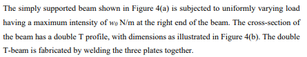
Transcribed Image Text:The simply supported beam shown in Figure 4(a) is subjected to uniformly varying load
having a maximum intensity of wo N/m at the right end of the beam. The cross-section of
the beam has a double T profile, with dimensions as illustrated in Figure 4(b). The double
T-beam is fabricated by welding the three plates together.
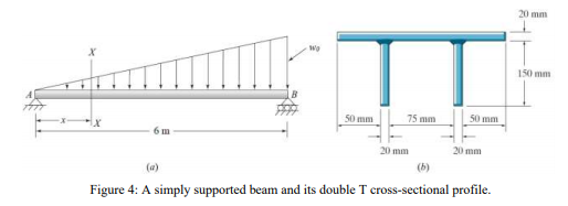
Transcribed Image Text:20 mm
150 mm
50 mm
75 mm
50 mm
6 m
20 mm
20 mm
(b)
(a)
Figure 4: A simply supported beam and its double T cross-sectional profile.
Expert Solution
This question has been solved!
Explore an expertly crafted, step-by-step solution for a thorough understanding of key concepts.

Step by step
Solved in 4 steps with 4 images

Knowledge Booster


Learn more about
Need a deep-dive on the concept behind this application? Look no further. Learn more about this topic, mechanical-engineering and related others by exploring similar questions and additional content below.Recommended textbooks for you
Mechanics of Materials (MindTap Course List)
Mechanical Engineering
ISBN:
9781337093347
Author:
Barry J. Goodno, James M. Gere
Publisher:
Cengage Learning
Mechanics of Materials (MindTap Course List)
Mechanical Engineering
ISBN:
9781337093347
Author:
Barry J. Goodno, James M. Gere
Publisher:
Cengage Learning