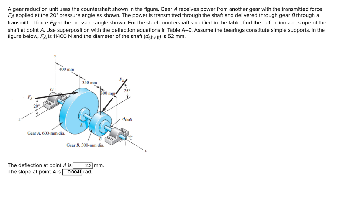
A gear reduction unit uses the countershaft shown in the figure. Gear A receives power from another gear with the transmitted force FA applied at the 20° pressure angle as shown. The power is transmitted through the shaft and delivered through gear B through a transmitted force Fg at the pressure angle shown. For the steel countershaft specified in the table, find the deflection and slope of the shaft at point A. Use superposition with the deflection equations in Table A-9. Assume the bearings constitute simple supports. In the figure below, FA is 11400 N and the diameter of the shaft (dshaft) is 52 mm. FA 20° 400 mm Gear A, 600-mm dia. 350 mm 300 mm Gear B, 300-mm dia. The deflection at point A is The slope at point A is 0.0041 rad. 2.2 mm. dshaft
A gear reduction unit uses the countershaft shown in the figure. Gear A receives power from another gear with the transmitted force FA applied at the 20° pressure angle as shown. The power is transmitted through the shaft and delivered through gear B through a transmitted force Fg at the pressure angle shown. For the steel countershaft specified in the table, find the deflection and slope of the shaft at point A. Use superposition with the deflection equations in Table A-9. Assume the bearings constitute simple supports. In the figure below, FA is 11400 N and the diameter of the shaft (dshaft) is 52 mm. FA 20° 400 mm Gear A, 600-mm dia. 350 mm 300 mm Gear B, 300-mm dia. The deflection at point A is The slope at point A is 0.0041 rad. 2.2 mm. dshaft

Mechanics of Materials (MindTap Course List)
9th Edition
ISBN:9781337093347
Author:Barry J. Goodno, James M. Gere
Publisher:Barry J. Goodno, James M. Gere
Chapter9: Deflections Of Beams
Section: Chapter Questions
Problem 9.3.23P: -23 The beam shown in the figure has a sliding support at A and a roller support at B. The sliding...

Related questions

Question
pls box ur answer and make sure ur units are correct
Transcribed Image Text:A gear reduction unit uses the countershaft shown in the figure. Gear A receives power from another gear with the transmitted force
FA applied at the 20° pressure angle as shown. The power is transmitted through the shaft and delivered through gear B through a
transmitted force Fg at the pressure angle shown. For the steel countershaft specified in the table, find the deflection and slope of the
shaft at point A. Use superposition with the deflection equations in Table A-9. Assume the bearings constitute simple supports. In the
figure below, FA is 11400 N and the diameter of the shaft (dshaft) is 52 mm.
20°
400 mm
Gear A, 600-mm dia.
350 mm
300 mm
B
Gear B, 300-mm dia.
The deflection at point A is
The slope at point A is 0.0041 rad.
2.2 mm.
FR
25°
dshaft
Expert Solution
This question has been solved!
Explore an expertly crafted, step-by-step solution for a thorough understanding of key concepts.

This is a popular solution!
Step 1: Write the given data.
VIEWStep 2: (a) Calculate the magnitude of force at point B by using torque equilibrium.
VIEWStep 3: Calculate the deflection at point A in y-direction.
VIEWStep 4: Calculate the deflection at point A in the z-direction.
VIEWStep 5: (b) Calculate the slope at A along the y-direction.
VIEWStep 6: Calculate the slope at A along the z-direction.
VIEWSolution
VIEW
Trending now
This is a popular solution!

Step by step
Solved in 7 steps

Knowledge Booster


Learn more about
Need a deep-dive on the concept behind this application? Look no further. Learn more about this topic, mechanical-engineering and related others by exploring similar questions and additional content below.Recommended textbooks for you
Mechanics of Materials (MindTap Course List)
Mechanical Engineering
ISBN:
9781337093347
Author:
Barry J. Goodno, James M. Gere
Publisher:
Cengage Learning
Mechanics of Materials (MindTap Course List)
Mechanical Engineering
ISBN:
9781337093347
Author:
Barry J. Goodno, James M. Gere
Publisher:
Cengage Learning