A loadline is drawn on the BJT transistor characteristics shown in Figure 3. f. Determine the value of Vcc and Rc for the fixed biased configuration shown in Figure 4. g. Show the operating point on figure 1 for IB=40μA. h. Determine the value of RB to establish the resulting operating point.VBE=0.7V. i Find the resulting values of Ice and Vere
A loadline is drawn on the BJT transistor characteristics shown in Figure 3. f. Determine the value of Vcc and Rc for the fixed biased configuration shown in Figure 4. g. Show the operating point on figure 1 for IB=40μA. h. Determine the value of RB to establish the resulting operating point.VBE=0.7V. i Find the resulting values of Ice and Vere

Introductory Circuit Analysis (13th Edition)
13th Edition
ISBN:9780133923605
Author:Robert L. Boylestad
Publisher:Robert L. Boylestad
Chapter1: Introduction
Section: Chapter Questions
Problem 1P: Visit your local library (at school or home) and describe the extent to which it provides literature...

Related questions
Question
Please solve f,g,h only
Figure-3 is the graph
show all steps clearly
Transcribed Image Text:10
9
7
6
3
2
Ic (mA)
5
10
110
15
80 μA
70 μA
20
50 μ
25
20 μA
10 μA
180
30
VCE (V)
Transcribed Image Text:RB
Vcc
IB
O
B
+
Rc.
VBE
Vcc
E
Ic
+
VCE
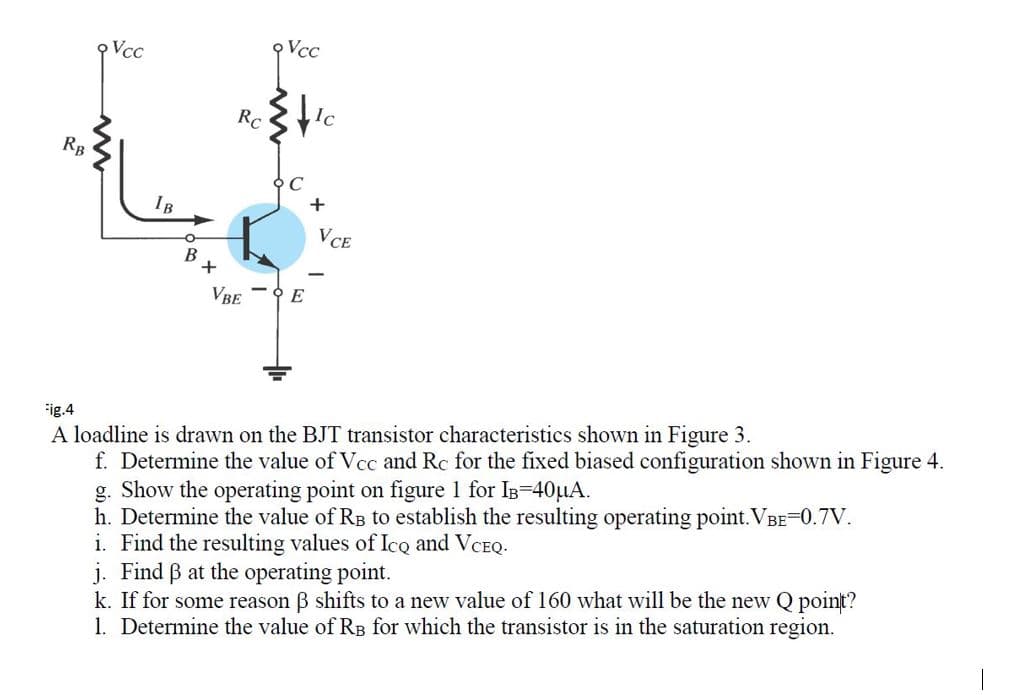
Fig.4
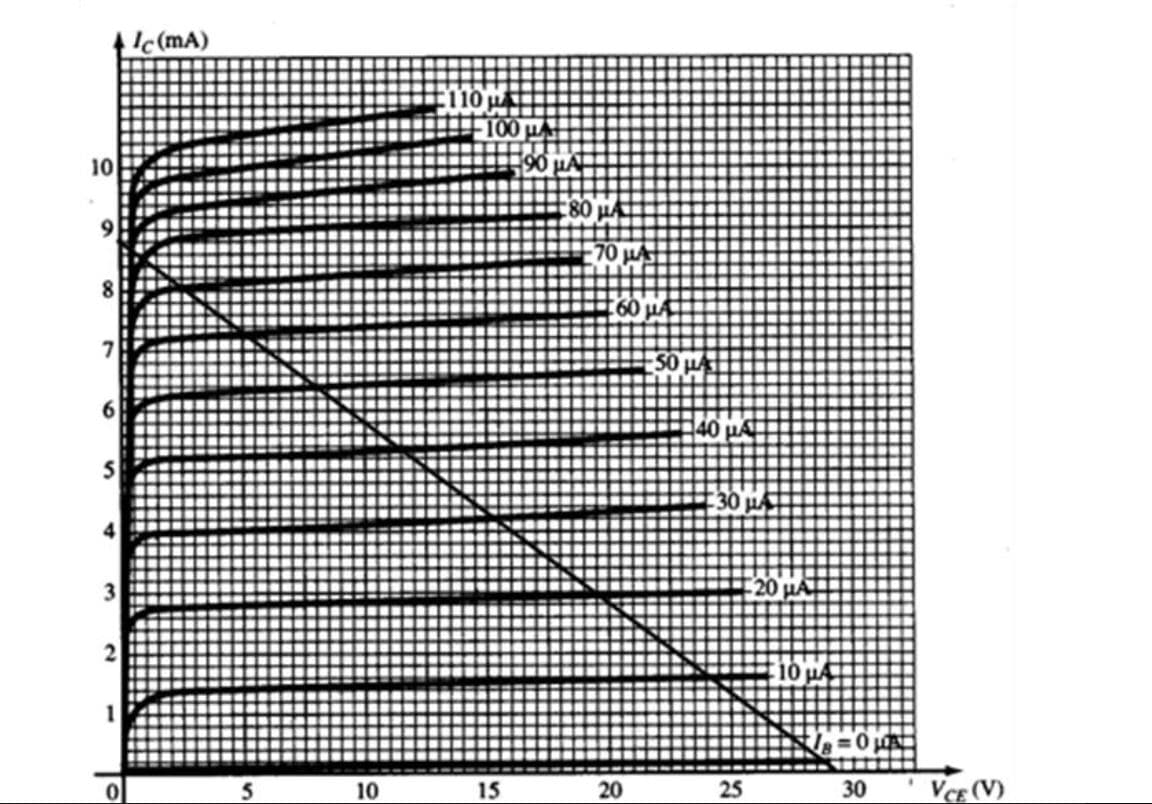
A loadline is drawn on the BJT transistor characteristics shown in Figure 3.
f. Determine the value of Vcc and Rc for the fixed biased
ation shown in Figure 4.
g. Show the operating point on figure 1 for IB=40μA.
h. Determine the value of RB to establish the resulting operating point.VBE=0.7V.
i. Find the resulting values of Ico and VCEQ.
j. Find ß at the operating point.
k. If for some reason 3 shifts to a new value of 160 what will be the new Q point?
1. Determine the value of RB for which the transistor is in the saturation region.
Expert Solution
This question has been solved!
Explore an expertly crafted, step-by-step solution for a thorough understanding of key concepts.

Step by step
Solved in 3 steps with 3 images

Knowledge Booster


Learn more about
Need a deep-dive on the concept behind this application? Look no further. Learn more about this topic, electrical-engineering and related others by exploring similar questions and additional content below.Recommended textbooks for you
Introductory Circuit Analysis (13th Edition)
Electrical Engineering
ISBN:
9780133923605
Author:
Robert L. Boylestad
Publisher:
PEARSON

Delmar's Standard Textbook Of Electricity
Electrical Engineering
ISBN:
9781337900348
Author:
Stephen L. Herman
Publisher:
Cengage Learning

Programmable Logic Controllers
Electrical Engineering
ISBN:
9780073373843
Author:
Frank D. Petruzella
Publisher:
McGraw-Hill Education
Introductory Circuit Analysis (13th Edition)
Electrical Engineering
ISBN:
9780133923605
Author:
Robert L. Boylestad
Publisher:
PEARSON
Delmar's Standard Textbook Of Electricity
Electrical Engineering
ISBN:
9781337900348
Author:
Stephen L. Herman
Publisher:
Cengage Learning
Programmable Logic Controllers
Electrical Engineering
ISBN:
9780073373843
Author:
Frank D. Petruzella
Publisher:
McGraw-Hill Education

Fundamentals of Electric Circuits
Electrical Engineering
ISBN:
9780078028229
Author:
Charles K Alexander, Matthew Sadiku
Publisher:
McGraw-Hill Education

Electric Circuits. (11th Edition)
Electrical Engineering
ISBN:
9780134746968
Author:
James W. Nilsson, Susan Riedel
Publisher:
PEARSON

Engineering Electromagnetics
Electrical Engineering
ISBN:
9780078028151
Author:
Hayt, William H. (william Hart), Jr, BUCK, John A.
Publisher:
Mcgraw-hill Education,