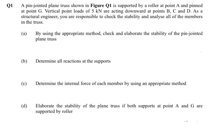
A pin-jointed plane truss shown in Figure Q1 is supported by a roller at point A and pinned at point G. Vertical point loads of 5 kN are acting downward at points B, C and D. As a structural engineer, you are responsible to check the stability and analyse all of the members in the truss. By using the appropriate method, check and elaborate the stability of the pin-jointed plane truss (а) (b) Determine all reactions at the supports (c) Determine the internal force of each member by using an appropriate method Elaborate the stability of the plane truss if both supports at point A and G are supported by roller (d)
A pin-jointed plane truss shown in Figure Q1 is supported by a roller at point A and pinned at point G. Vertical point loads of 5 kN are acting downward at points B, C and D. As a structural engineer, you are responsible to check the stability and analyse all of the members in the truss. By using the appropriate method, check and elaborate the stability of the pin-jointed plane truss (а) (b) Determine all reactions at the supports (c) Determine the internal force of each member by using an appropriate method Elaborate the stability of the plane truss if both supports at point A and G are supported by roller (d)

Chapter2: Loads On Structures
Section: Chapter Questions
Problem 1P

Related questions

Question
Transcribed Image Text:A pin-jointed plane truss shown in Figure Q1 is supported by a roller at point A and pinned
at point G. Vertical point loads of 5 kN are acting downward at points B, C and D. As a
structural engineer, you are responsible to check the stability and analyse all of the members
in the truss.
Q1
(a)
By using the appropriate method, check and elaborate the stability of the pin-jointed
plane truss
(b)
Determine all reactions at the supports
(c)
Determine the internal force of each member by using an appropriate method
(d)
Elaborate the stability of the plane truss if both supports at point A and G are
supported by roller
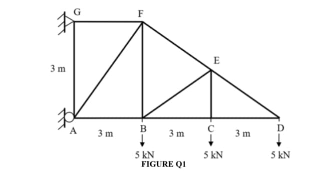
Transcribed Image Text:G
F
E
3 m
A
3 m
B
3 m
3 m
5 kN
FIGURE Q1
5 kN
5 kN
Expert Solution
This question has been solved!
Explore an expertly crafted, step-by-step solution for a thorough understanding of key concepts.

Step by step
Solved in 3 steps with 2 images

Knowledge Booster


Learn more about
Need a deep-dive on the concept behind this application? Look no further. Learn more about this topic, civil-engineering and related others by exploring similar questions and additional content below.Recommended textbooks for you

Structural Analysis (10th Edition)
Civil Engineering
ISBN:
9780134610672
Author:
Russell C. Hibbeler
Publisher:
PEARSON

Principles of Foundation Engineering (MindTap Cou…
Civil Engineering
ISBN:
9781337705028
Author:
Braja M. Das, Nagaratnam Sivakugan
Publisher:
Cengage Learning
Structural Analysis (10th Edition)
Civil Engineering
ISBN:
9780134610672
Author:
Russell C. Hibbeler
Publisher:
PEARSON
Principles of Foundation Engineering (MindTap Cou…
Civil Engineering
ISBN:
9781337705028
Author:
Braja M. Das, Nagaratnam Sivakugan
Publisher:
Cengage Learning

Fundamentals of Structural Analysis
Civil Engineering
ISBN:
9780073398006
Author:
Kenneth M. Leet Emeritus, Chia-Ming Uang, Joel Lanning
Publisher:
McGraw-Hill Education


Traffic and Highway Engineering
Civil Engineering
ISBN:
9781305156241
Author:
Garber, Nicholas J.
Publisher:
Cengage Learning