A schematic design of a full-wave bridge type power supply is given below. Provide the appropriate values for the inductors, diodes, capacitor and resistors, such that the output DC voltage is 6.2 V and the max. output power for the load resistance is 20 mW (percentage error for output voltage and output power is 2%). AC voltage source: Amplitude=311.13, Freq=60, DC offset= 0. For the rectifier part, choose diodes with an appropriate PIV rating. Show all the formulas and computations involved in acquiring the values for the inductors, diodes, capacitor and resistors. In choosing your Zener diode, consider the output voltage and the output current. Note that the output current should be the minimum Zener current. For the value of the series resistor RS, choose a lower value for less ripple but always consider the required output voltage. The ripple voltage peak-to-peak value should be less than or equal to 1% of the required output voltage. Use the formula below for choosing the value of capacitor, C1. Always choose the higher value for the capacitance and consider the voltage across C1.
A schematic design of a full-wave bridge type power supply is given below. Provide the appropriate values for the inductors, diodes, capacitor and resistors, such that the output DC voltage is 6.2 V and the max. output power for the load resistance is 20 mW (percentage error for output voltage and output power is 2%). AC voltage source: Amplitude=311.13, Freq=60, DC offset= 0. For the rectifier part, choose diodes with an appropriate PIV rating. Show all the formulas and computations involved in acquiring the values for the inductors, diodes, capacitor and resistors. In choosing your Zener diode, consider the output voltage and the output current. Note that the output current should be the minimum Zener current. For the value of the series resistor RS, choose a lower value for less ripple but always consider the required output voltage. The ripple voltage peak-to-peak value should be less than or equal to 1% of the required output voltage. Use the formula below for choosing the value of capacitor, C1. Always choose the higher value for the capacitance and consider the voltage across C1.

Introductory Circuit Analysis (13th Edition)
13th Edition
ISBN:9780133923605
Author:Robert L. Boylestad
Publisher:Robert L. Boylestad
Chapter1: Introduction
Section: Chapter Questions
Problem 1P: Visit your local library (at school or home) and describe the extent to which it provides literature...

Related questions

Question
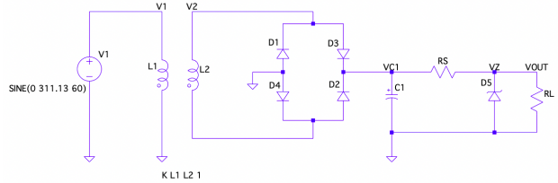
A schematic design of a full-wave bridge type power supply is given below. Provide the appropriate values for the inductors, diodes, capacitor and resistors, such that the output DC voltage is 6.2 V and the max. output power for the load resistance is 20 mW (percentage error for output voltage and output power is 2%). AC voltage source: Amplitude=311.13, Freq=60, DC offset= 0. For the rectifier part, choose diodes with an appropriate PIV rating. Show all the formulas and computations involved in acquiring the values for the inductors, diodes, capacitor and resistors.
- In choosing your Zener diode, consider the output voltage and the output current. Note that the output current should be the minimum Zener current.
- For the value of the series resistor RS, choose a lower value for less ripple but always consider the required output voltage.
- The ripple voltage peak-to-peak value should be less than or equal to 1% of the required output voltage. Use the formula below for choosing the value of capacitor, C1. Always choose the higher value for the capacitance and consider the voltage across C1.
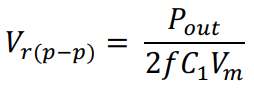
Transcribed Image Text:Pout
Vr(p-p)
2f C,Vm
т
Transcribed Image Text:V1
V2
D1
D3
V1
RS
L1
L2
VC1
VZ
VOUT
SINE(O 311.13 60)
D4
D2
C1
D5
RL
KLI L2 1
Expert Solution
This question has been solved!
Explore an expertly crafted, step-by-step solution for a thorough understanding of key concepts.

Step by step
Solved in 4 steps with 4 images

Knowledge Booster


Learn more about
Need a deep-dive on the concept behind this application? Look no further. Learn more about this topic, electrical-engineering and related others by exploring similar questions and additional content below.Recommended textbooks for you
Introductory Circuit Analysis (13th Edition)
Electrical Engineering
ISBN:
9780133923605
Author:
Robert L. Boylestad
Publisher:
PEARSON

Delmar's Standard Textbook Of Electricity
Electrical Engineering
ISBN:
9781337900348
Author:
Stephen L. Herman
Publisher:
Cengage Learning

Programmable Logic Controllers
Electrical Engineering
ISBN:
9780073373843
Author:
Frank D. Petruzella
Publisher:
McGraw-Hill Education
Introductory Circuit Analysis (13th Edition)
Electrical Engineering
ISBN:
9780133923605
Author:
Robert L. Boylestad
Publisher:
PEARSON
Delmar's Standard Textbook Of Electricity
Electrical Engineering
ISBN:
9781337900348
Author:
Stephen L. Herman
Publisher:
Cengage Learning
Programmable Logic Controllers
Electrical Engineering
ISBN:
9780073373843
Author:
Frank D. Petruzella
Publisher:
McGraw-Hill Education

Fundamentals of Electric Circuits
Electrical Engineering
ISBN:
9780078028229
Author:
Charles K Alexander, Matthew Sadiku
Publisher:
McGraw-Hill Education

Electric Circuits. (11th Edition)
Electrical Engineering
ISBN:
9780134746968
Author:
James W. Nilsson, Susan Riedel
Publisher:
PEARSON

Engineering Electromagnetics
Electrical Engineering
ISBN:
9780078028151
Author:
Hayt, William H. (william Hart), Jr, BUCK, John A.
Publisher:
Mcgraw-hill Education,