A self-balancing robot is an inverted-pendulum example problem. The idea is to keep the robot upright by driving the wheels towards the leaning angle theta. When the robot is tilting forward, the wheels should be driven forward with a specific acceleration to counter the tilting. This will keep the robot in an upright position at all times. The block diagram of the system shown in Figure 3 with transfer function of G(s) = 1/s(s+1)(s2+4s+20) and H(s) = 1. a) Sketch the root locus by indicating the poles and zeros location on the loci. b) Locate the asymptotes on the root locus in (a). c) Determine the range of K to keep the system stable. d) Identify the jco axis crossing on the root locus in (a).
A self-balancing robot is an inverted-pendulum example problem. The idea is to keep the robot upright by driving the wheels towards the leaning angle theta. When the robot is tilting forward, the wheels should be driven forward with a specific acceleration to counter the tilting. This will keep the robot in an upright position at all times. The block diagram of the system shown in Figure 3 with transfer function of G(s) = 1/s(s+1)(s2+4s+20) and H(s) = 1. a) Sketch the root locus by indicating the poles and zeros location on the loci. b) Locate the asymptotes on the root locus in (a). c) Determine the range of K to keep the system stable. d) Identify the jco axis crossing on the root locus in (a).

Introductory Circuit Analysis (13th Edition)
13th Edition
ISBN:9780133923605
Author:Robert L. Boylestad
Publisher:Robert L. Boylestad
Chapter1: Introduction
Section: Chapter Questions
Problem 1P: Visit your local library (at school or home) and describe the extent to which it provides literature...

Related questions
Question
A self-balancing robot is an inverted-pendulum example problem. The idea is to keep the
robot upright by driving the wheels towards the leaning angle theta. When the robot is tilting
forward, the wheels should be driven forward with a specific acceleration to counter the
tilting. This will keep the robot in an upright position at all times. The block diagram of the
system shown in Figure 3 with transfer function of G(s) = 1/s(s+1)(s2+4s+20) and H(s) = 1.
a) Sketch the root locus by indicating the poles and zeros location on the loci.
b) Locate the asymptotes on the root locus in (a).
c) Determine the range of K to keep the system stable.
d) Identify the jco axis crossing on the root locus in (a).
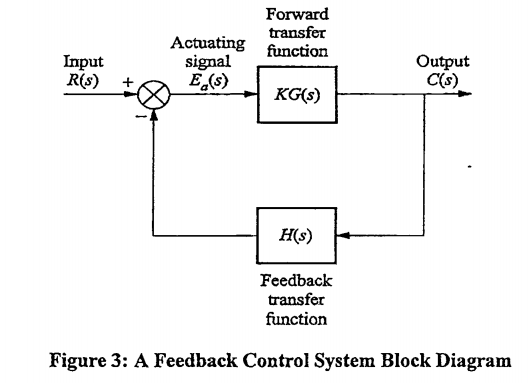
Transcribed Image Text:Input
R(s)
Actuating
signal
E (s)
Forward
transfer
function
KG(s)
H(s)
Feedback
transfer
function
Output
C(s)
Figure 3: A Feedback Control System Block Diagram
Expert Solution
This question has been solved!
Explore an expertly crafted, step-by-step solution for a thorough understanding of key concepts.

Step by step
Solved in 4 steps with 4 images

Knowledge Booster


Learn more about
Need a deep-dive on the concept behind this application? Look no further. Learn more about this topic, electrical-engineering and related others by exploring similar questions and additional content below.Recommended textbooks for you
Introductory Circuit Analysis (13th Edition)
Electrical Engineering
ISBN:
9780133923605
Author:
Robert L. Boylestad
Publisher:
PEARSON

Delmar's Standard Textbook Of Electricity
Electrical Engineering
ISBN:
9781337900348
Author:
Stephen L. Herman
Publisher:
Cengage Learning

Programmable Logic Controllers
Electrical Engineering
ISBN:
9780073373843
Author:
Frank D. Petruzella
Publisher:
McGraw-Hill Education
Introductory Circuit Analysis (13th Edition)
Electrical Engineering
ISBN:
9780133923605
Author:
Robert L. Boylestad
Publisher:
PEARSON
Delmar's Standard Textbook Of Electricity
Electrical Engineering
ISBN:
9781337900348
Author:
Stephen L. Herman
Publisher:
Cengage Learning
Programmable Logic Controllers
Electrical Engineering
ISBN:
9780073373843
Author:
Frank D. Petruzella
Publisher:
McGraw-Hill Education

Fundamentals of Electric Circuits
Electrical Engineering
ISBN:
9780078028229
Author:
Charles K Alexander, Matthew Sadiku
Publisher:
McGraw-Hill Education

Electric Circuits. (11th Edition)
Electrical Engineering
ISBN:
9780134746968
Author:
James W. Nilsson, Susan Riedel
Publisher:
PEARSON

Engineering Electromagnetics
Electrical Engineering
ISBN:
9780078028151
Author:
Hayt, William H. (william Hart), Jr, BUCK, John A.
Publisher:
Mcgraw-hill Education,