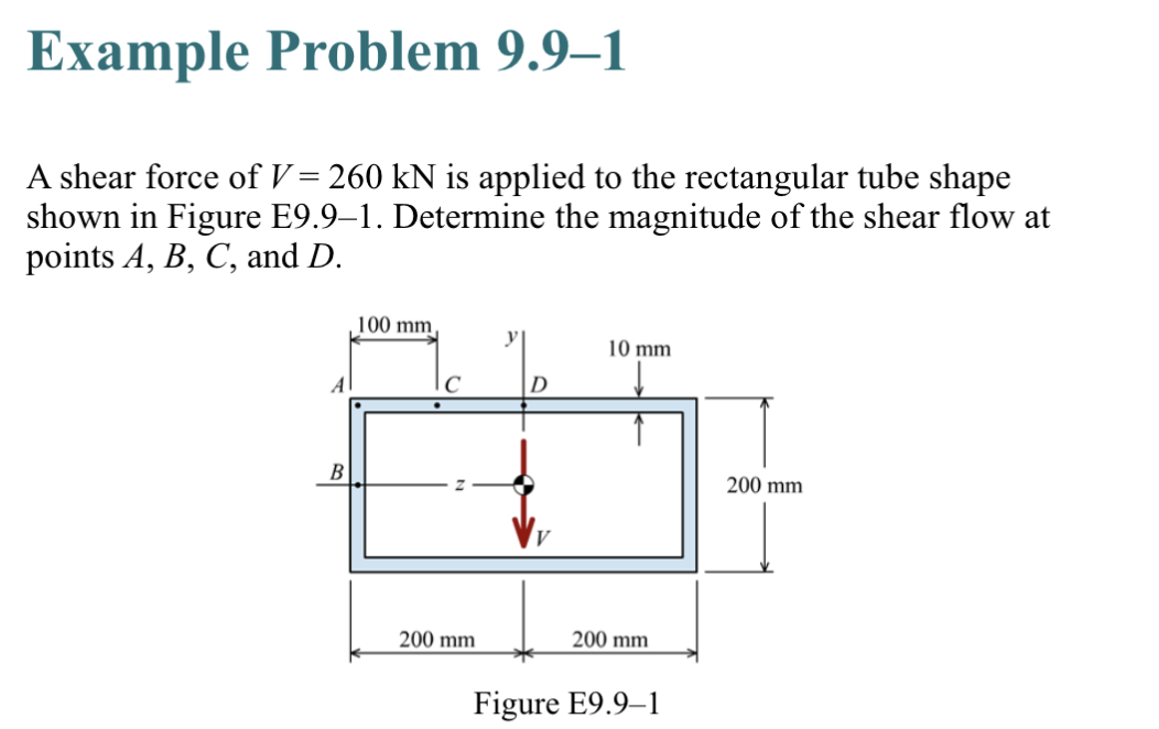
A shear force of V = 260 kN is applied to the rectangular tube shape shown in Figure E9.9-1. Determine the magnitude of the shear flow at points A, B, C, and D. A B 100 mm IC 200 mm D 10 mm 200 mm Figure E9.9-1 200 mm
Q: Р. What is the maximum simultaneous axial tension load, Pu, capable of being resisted by a W18x35…
A: Tensile load Tensile load is the ratio of the applied force to the unit area that causes the…
Q: Determine the maximum moment, M, for the beam and loading given if w = 2.2 kip/ft and P = 27 kip. Be…
A:
Q: Determine the percent reduction n in the polar moment of inertia of the square plate due to the…
A:
Q: Which of the following most nearly gives the required effective flange width of an interior beam? a.…
A:
Q: SITUATION 1-A 1000 cc soil sample taken from the field weighs 1950 grams. Laboratory analysis shows…
A:
Q: Problem 3.25 The acrylic plastic rod is 200 mm long and 25 mm in diameter. Figure 1 of 1 Part A If…
A: given :
Q: the cross-sectional area of the bar 1 of the two bars supported on the left and right sides is 1.2…
A: Given data: ∆T=99∘CE=207 GPa Bar 1: L1=13.3 mA=1.2 cm2α1=20.9×10⁻⁶ /K Bar 2: L2=7.8 mA2=3…
Q: A truly supported beam 230 x 550 mm effective is reinforcerd with 4 16 - Fe 415. find total restrict…
A:
Q: Two pieces of wood are glued together, find the maximum load which the glued wood could carry that…
A: Given DataTwo wooden pieces are glued together.Given angle of glued section θ=30°The maximum normal…
Q: Draw the shear force (S.F) and banding moment (B.M) diagrams for the beam and loading shown in…
A:
Q: Question -for a traffic Stream speed density relationship was found to be Determine U= 42-46-D-22 K…
A:
Q: Vertical reaction developed at B
A:
Q: DETERMINE THE SHEAR AND MOMENT DIAGRAM OF THE BEAMS SHOWN. TAKE NOTE FOR THE LOCATIONS OF ZERO…
A:
Q: Determine the deflection at the free end of the cantilever beam. E = 250 GPa and 1 = 420 x 106 mm4…
A:
Q: A steel column is pinned at both ends and has a buckling load of 200 kN. If the column is restrained…
A: Given: A steel column is pinned at both ends and has a buckling load of 200 kN. The column is…
Q: Problem 3.25 The acrylic plastic rod is 200 mm long and 25 mm in diameter. Figure 1 of 1 200 mm Part…
A:
Q: Determine the centroidal y-coordinate (in mm, round=off to 2 decimal places) of the plane curve…
A: Given: Dimensions of plane curve To find: Centriodal y coordinate
Q: SITUATION 4: Results from liquid and plastic limit tests conducted on a soil are given in the table.…
A: Given values: Results from Casagrande's test for liquid and plastic limits on soil: No: of blows…
Q: Compute the value of the following using 3 decimal places: - Moment of Inertia about the X-axis -…
A: As per the guidelines of Bartleby we are supposed to answer only first three sub questions.
Q: Part A Replace the loading by an equivalent force. Express your answer to three significant figures…
A: Given :
Q: Determine the x-and y-coordinates of the centroid of the shaded area. 25 Answers: F= 150 y= 175 75…
A:
Q: Draw the shear and moment diagrams for the cantilever beam shown in the figure below. Label all…
A: Given :
Q: 11-17. Determine the moments at the fixed support A and joint D and then draw the moment diagram for…
A: Given data
Q: order to eliminate the sag and temperature correction, given the following? a = 6x10^-6 m^2 E =…
A: Temperature correction :CT=Tm-ToLαCT=20-22300.0000116=0.696mm
Q: Design for the maximum negative moment, maximum positive moment, and maximum shear of a continuous…
A:
Q: 7. The 50-mm diameter rubber rod is placed in a hole with rigid lubricated walls. There is no…
A:
Q: Determine the design axial and moment capacity at eccentricity of 95 mm.
A:
Q: An open rectangular tank of dimensions 4mx3mx2m contains water to a height of 1.6m. It is then…
A:
Q: 1 A W C L = 20 m B I W310 x 38.7 For the beam and loading shown, knowing that a = 10 m, w = 2020…
A: Given data
Q: Find the centroid of given composite figure. Set- up the reference axis on the lower left corner.…
A:
Q: In the beam shown, take W1 = 9 kN/m, M1 = 25 kN-m, and P1 = 22 kN. a) Determine the shear at "D"
A:
Q: Determine the location of the resultant of a uniform varying load if magnitude is 3kn/m with a total…
A:
Q: 11-17. Determine the moments at the fixed support A and joint D and then draw the moment diagram for…
A: In the structure the loading is given as uniformly distributed loading. By using Moment Distribution…
Q: PROBLEM NO. 2 The tower shown is subjected to three forces as follows: F₁ = 4 kN, F₂ = 6 kN, F3 = 6…
A:
Q: The vertical portion of the press shown consists of a rectangular tube of wall thickness t = 10 mm.…
A: Given :
Q: Q.1 Determine the reaction at supports and the force in AB, BC, and BD members of and indicate…
A:
Q: Determine the x-, y-, and z-coordinates of the mass center of the body constructed of three pieces…
A: Given Required x, y and z coordinate
Q: The structure is worked up by El-Centro earthquake with zeta=five%. it's far required to investigate…
A:
Q: Question 1: Consider a 600 mm deep reinforced concrete cantilever beam supported by a 600 mm square…
A: Hi! Thank you for the question As per the honor code, We’ll answer the second question since the…
Q: 1. The 6061-T6 aluminum shaft shown below is loaded axially. The output from a strain gage mounted…
A:
Q: The mean dimensions of the cross section of the leading edge and torsion box of an airplane wing can…
A: Given :
Q: The two shafts are made of A992 steel. Each has a diameter of 0.9 in., and they are supported by…
A: Given :
Q: 6. The wood pole shown in the Figure 4 is supported by two cables of inch diameter. The turnbuckles…
A: Solution-Cables transmit force to the pole. Suppose that the cable direction is the same as pole…
Q: A 2m W₁ * V * * * * * B 5m 2m P₁ P₂ V V D 5 F 1m 1m tt W2 3m G 1m
A:
Q: Determine the product of inertia of the shaded area about the x-y axes.
A: Given :
Q: Determine the moment of inertia (mm4) ly of the composite area shown with respect to y-axis if a =…
A: Let Area 1 = Whole rectangular = (b + c) X a Area 2 = quarter circle with radius r Area 3 = Triangle…
Q: Situation: A T-beam is reinforced with 8-32mm diameter tension bars with an effective depth of…
A: Solution: Given: fc = 27.60 MPa fy = 413.7 MPa d = 700 mm h = 800 mm b = 350 mm bf = 750 mm
Q: A prismatic pile 12 m long is to be lifted by a crane from a horizontal position to a vertical…
A:
Q: Complete Solution. Thank you! I'll rate asap. Given: a = 23.5 kN, b = 22.5 kN, c = 4.5 m…
A: Hi! Thank you for the question, As per the honor code, we are allowed to answer three sub-parts at a…
Q: A 450 mm x 550 mm TIED column is reinforced with 12-20 distributed evenly on the two short sides…
A:
Step by step
Solved in 2 steps with 3 images
- Consider the steady open channel flow of water in the smooth constriction shown in plan view in Figure P10.46. At position 1, the depth is Y1, the width is B1 and the Froude number F1 = 4. A similar notation is used at positions 2, 3 and 4. A hydraulic jump is observed just downstream of position 2 where the Froude number F2 = 2. You may assume one-dimensional flow. (a) Find Y2, the depth at position 2, in terms of Y1. (b) Find Y3, the depth just downstream of the hydraulic jump, in terms of Y1. (c) Find F3, the Froude number just downstream of the hydraulic jump. (d) Find F4, the Froude number at the exit, given that Y3/Y4 = 1.2. (e) Find B4/B1.The tank shown in the figure is 3 m wide into the paper. Neglect atmospheric pressure. Use ?????? = 9.79 kN/m³. Determine the following: A. vertical component of the total hydrostatic force on the quarter circle panel AB in kN B. Resultant hydrostatic force acting on the quarter circle panel AB in kN C. Angle that the resultant hydrostatic force make with the horizontal in degrees.Given Figure E1, draw the active earth pressure distribution. Use gw = 9.81 kN/m3. Determine the magnitude and location of the active thrust.
- 6.3 Determine the wall shearing stress in a pipe of diameter 100mm, which conveys water. The velocities at the half the diameter from boundary is 2 m/s. The local velocity at 20mm from the pipe wall is 1.5m/s and the flow is turbulent,Determine the head loss in the "smooth" pipe in meters if its friction factor is 0.014. a.12.9517 b.39.5136 c.30.4889 d.99.9358 What gage pressure p1 in kPa, is needed to provide the given flow rate? a.1692 kPa b.1121 kPa c.1328 kPa d.1725 kPa4. A reservoir supplies water to a horizontal 6′′ pipe 800 ft long. The pipe flows full and discharges into the atmosphere at the rate of 2.23 cfs. What is the pressure in psi midway in the pipe, assuming the only lost head is 6.20 ft in each 100 ft of length? indicaye free body diagram
- Problem 4 A square gate (2m on each side) is submerged vertically in water such that the upper edge of the gateis at a depth of 0.5 m from the watersurface. Draw the figure and find the hydrostatic force and the location of the center of pressure.Consider a rectangular channel of width b=7.5 m, in which the hydraulic jump occurs and one of its stays is equal to 45 cm. A flow rate Q=54 m3/s passes through the channel. Determine: a) the other conjugate tie rod b) energy losses c) type of jump that occurs d) jump lengthA trapezoidal channel is discharging 20.40 m^3/sec at a depth of 1.2 m and a base width of 6 m. The side slope is 2 horizontal to 1 vertical. n = 0.014. Compute the slope of the energy grade line. a. 0.00094 b. 0.00015 c. 0.00021 d. 0.00124 compute the specific energy. a. 1.10 m b. 1.84 m c. 1.62 m d. 1.41 m compute the average shearing stress on the boundary surface. a. 3.50 Pa b. 8.18 Pa c. 7.11 Pa d. 5.04 Pa
- gage pressure at point 1 = 275 kPa velocity = 3 meters/sec *Neglect friction* Given the figure, determine the total longitudinal thrust applied on the horizontal pipe.A circular gate 1.5 m in diameter is inclined at an angle of 45 deg.. Fresh water strands on one side of the gate to a height of 10 m above the center of the gate. Compute the location of the Hydrostatic force measured from the bottom (Ybottom) in metersIn the cage system below; It is under the effect of a P=250 kN load acting at an angle of θ=30° from the point C. Calculate the horizontal displacement (cm) to the right at point C. (E=2000 kN/cm² and A=50 cm² will be taken for all bars.)