A single phase full-bridge inverter is supplying a series RL load (R=202, L=0.04H) from a 300V DC source. The full square-wave output waveform period is 8ms. The controlled switches are MOSFETS. Assume the circuit is ideal. a. Sketch the scaled load current for first two periods from starting by calculating. (Assuming i,=0 at =0) b. For steady state operation find the maximum and minimum vahues of load current. c. Calculate the MOSFET conduction time and the mean value of MOSFET current.
A single phase full-bridge inverter is supplying a series RL load (R=202, L=0.04H) from a 300V DC source. The full square-wave output waveform period is 8ms. The controlled switches are MOSFETS. Assume the circuit is ideal. a. Sketch the scaled load current for first two periods from starting by calculating. (Assuming i,=0 at =0) b. For steady state operation find the maximum and minimum vahues of load current. c. Calculate the MOSFET conduction time and the mean value of MOSFET current.

Introductory Circuit Analysis (13th Edition)
13th Edition
ISBN:9780133923605
Author:Robert L. Boylestad
Publisher:Robert L. Boylestad
Chapter1: Introduction
Section: Chapter Questions
Problem 1P: Visit your local library (at school or home) and describe the extent to which it provides literature...

Related questions
Question
100%
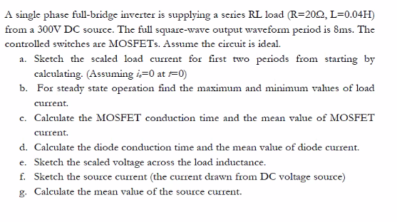
Transcribed Image Text:A single phase full-bridge inverter is supplying a series RL load (R=202, L=0.04H)
from a 300V DC source. The full square-wave output waveform period is 8ms. The
controlled switches are MOSFETS. Assume the circuit is ideal.
a. Sketch the scaled load current for first two periods from starting by
calculating. (Assuming i=0 at =0)
b. For steady state operation find the maximum and minimum vahues of load
current.
c. Calculate the MOSFET conduction time and the mean value of MOSFET
current.
d. Calculate the diode conduction time and the mean value of diode current.
e. Sketch the scaled voltage across the load inductance.
f. Sketch the source current (the current drawn from DC voltage source)
g. Calculate the mean value of the source current.
Expert Solution
This question has been solved!
Explore an expertly crafted, step-by-step solution for a thorough understanding of key concepts.

Step by step
Solved in 4 steps with 2 images

Knowledge Booster


Learn more about
Need a deep-dive on the concept behind this application? Look no further. Learn more about this topic, electrical-engineering and related others by exploring similar questions and additional content below.Recommended textbooks for you
Introductory Circuit Analysis (13th Edition)
Electrical Engineering
ISBN:
9780133923605
Author:
Robert L. Boylestad
Publisher:
PEARSON

Delmar's Standard Textbook Of Electricity
Electrical Engineering
ISBN:
9781337900348
Author:
Stephen L. Herman
Publisher:
Cengage Learning

Programmable Logic Controllers
Electrical Engineering
ISBN:
9780073373843
Author:
Frank D. Petruzella
Publisher:
McGraw-Hill Education
Introductory Circuit Analysis (13th Edition)
Electrical Engineering
ISBN:
9780133923605
Author:
Robert L. Boylestad
Publisher:
PEARSON
Delmar's Standard Textbook Of Electricity
Electrical Engineering
ISBN:
9781337900348
Author:
Stephen L. Herman
Publisher:
Cengage Learning
Programmable Logic Controllers
Electrical Engineering
ISBN:
9780073373843
Author:
Frank D. Petruzella
Publisher:
McGraw-Hill Education

Fundamentals of Electric Circuits
Electrical Engineering
ISBN:
9780078028229
Author:
Charles K Alexander, Matthew Sadiku
Publisher:
McGraw-Hill Education

Electric Circuits. (11th Edition)
Electrical Engineering
ISBN:
9780134746968
Author:
James W. Nilsson, Susan Riedel
Publisher:
PEARSON

Engineering Electromagnetics
Electrical Engineering
ISBN:
9780078028151
Author:
Hayt, William H. (william Hart), Jr, BUCK, John A.
Publisher:
Mcgraw-hill Education,