A synchronous logic circuit has one JK flip-flop, one D flip-flop, and one input. There is no output at the circuit. The input is represented with the letter X. Y, is the output of D flip-flop, Yo is the output of JK flip-flop respectively. The logic functions for the flip-flop's inputs are given below. J = XY, K = X+ Y,, D = X(Y, + Y1) %3D %3D Draw the state diagram of the synchronous logic circuit. Note: (Y,Yo)2 shall represent the state.
A synchronous logic circuit has one JK flip-flop, one D flip-flop, and one input. There is no output at the circuit. The input is represented with the letter X. Y, is the output of D flip-flop, Yo is the output of JK flip-flop respectively. The logic functions for the flip-flop's inputs are given below. J = XY, K = X+ Y,, D = X(Y, + Y1) %3D %3D Draw the state diagram of the synchronous logic circuit. Note: (Y,Yo)2 shall represent the state.

Introductory Circuit Analysis (13th Edition)
13th Edition
ISBN:9780133923605
Author:Robert L. Boylestad
Publisher:Robert L. Boylestad
Chapter1: Introduction
Section: Chapter Questions
Problem 1P: Visit your local library (at school or home) and describe the extent to which it provides literature...

Related questions
Question
100%
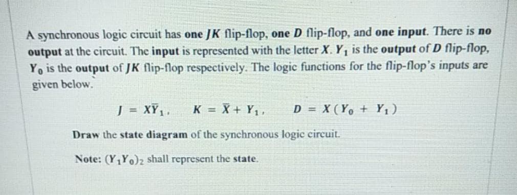
Transcribed Image Text:A synchronous logic circuit has one JK flip-flop, one D flip-flop, and one input. There is no
output at the circuit. The input is represented with the letter X. Y, is the output of D flip-flop,
Yo is the output of JK flip-flop respectively. The logic functions for the flip-flop's inputs are
given below.
J = XY,,
K = X + Y,,
D = X(Y, + Y,)
!!
Draw the state diagram of the synchronous logic circuit.
Note: (Y,Yo)z shall represent the state.
Expert Solution
This question has been solved!
Explore an expertly crafted, step-by-step solution for a thorough understanding of key concepts.

Step by step
Solved in 5 steps with 5 images

Knowledge Booster


Learn more about
Need a deep-dive on the concept behind this application? Look no further. Learn more about this topic, electrical-engineering and related others by exploring similar questions and additional content below.Recommended textbooks for you
Introductory Circuit Analysis (13th Edition)
Electrical Engineering
ISBN:
9780133923605
Author:
Robert L. Boylestad
Publisher:
PEARSON

Delmar's Standard Textbook Of Electricity
Electrical Engineering
ISBN:
9781337900348
Author:
Stephen L. Herman
Publisher:
Cengage Learning

Programmable Logic Controllers
Electrical Engineering
ISBN:
9780073373843
Author:
Frank D. Petruzella
Publisher:
McGraw-Hill Education
Introductory Circuit Analysis (13th Edition)
Electrical Engineering
ISBN:
9780133923605
Author:
Robert L. Boylestad
Publisher:
PEARSON
Delmar's Standard Textbook Of Electricity
Electrical Engineering
ISBN:
9781337900348
Author:
Stephen L. Herman
Publisher:
Cengage Learning
Programmable Logic Controllers
Electrical Engineering
ISBN:
9780073373843
Author:
Frank D. Petruzella
Publisher:
McGraw-Hill Education

Fundamentals of Electric Circuits
Electrical Engineering
ISBN:
9780078028229
Author:
Charles K Alexander, Matthew Sadiku
Publisher:
McGraw-Hill Education

Electric Circuits. (11th Edition)
Electrical Engineering
ISBN:
9780134746968
Author:
James W. Nilsson, Susan Riedel
Publisher:
PEARSON

Engineering Electromagnetics
Electrical Engineering
ISBN:
9780078028151
Author:
Hayt, William H. (william Hart), Jr, BUCK, John A.
Publisher:
Mcgraw-hill Education,