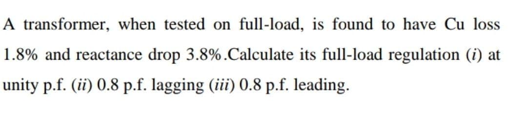
A transformer, when tested on full-load, is found to have Cu loss 1.8% and reactance drop 3.8%. Calculate its full-load regulation (i) at unity p.f. (ii) 0.8 p.f. lagging (iii) 0.8 p.f. leading.
Q: Electrical Engineering help. fundamental btw For the circuit of Figure 2.41, determine the…
A: the solution is given below
Q: N-channel enhancement MOSFET control voltage is applied at the controlling the current that is. d —…
A: We need to select correct option for given statement .
Q: reduce the following equation XY + ~X~Y + (~X+~Y) + (~X+Y) xy ~X 01 ~x~y+~xy
A: Given: Function is XY+~X~Y+X~+~Y+~X+Y
Q: A small DC machine has a torque constant of 0.47NM/A and an armature resistance of 4 ohms. It is…
A: Torque constant=0.47 Nm/A=KTSpeed=525 rpmRa=4ΩKT=TIa=EgIa2πN/60Iae.m.f.=0.47×2π×52560=25.82 VOutput…
Q: Given the NMOS circuit in Figure 2 with VDD = 18 V and the following transistor parameters: V₁=0.8…
A:
Q: (a) Draw the state transition table and the state diagram for the circuit shown in Figure Q1(a). Is…
A: The solution is given below
Q: Give the Area of application of HPS lamps 1. 2. 3. 4.
A: HPS Lamps stands for High Pressure Sodium Lamps. It has many applications like daily usage.
Q: Given the magnetic field vector potential: A= y z ax +2 x y z ay-xz az (A/m), find: (1) magnetic…
A:
Q: Find the Q point value of the diode current and the voltage gain Av in the following circuit: 700Ω…
A: Diode It is an unidirectional electrical device, which allows current to flow only in one specific…
Q: A coil having a resistance of 45 and an inductance of 0.4 H is connected in parallel with a…
A:
Q: Simplify the given block diagram below into a single block. G8(s)- R(s) + G6(s)- G1(s) G3(s) C(s)…
A: Block Diagram Reduction Rules: Follow these rules for simplifying (reducing) the block diagram,…
Q: Find the wind speed in K/h needed to generate 4641.7Kw for a wind turbine with a height of 32.13m…
A: Given data, Power generated P = 4641.7 KW Height h = 32.13 m Density ρ=6.125 kg5 m3=1.225 kg/m3,
Q: bads: Load 1: 18 kVA at 0.8 pf lagging Load 2: 10 kW at 0.6 pf leading Load 3: unknown If the line…
A: Solve the problem
Q: 1. What are the basic components of RC Oscillator Circuit? 2. How is the resonant frequency being…
A: As per the guidelines of bartleyby I need to answer first three questions only.
Q: Digit keys +5 V 1 kg For switch bounce Q >T OS ō tp-20 ms Pull-up resistor for each input 74LS147…
A: A basic logic circuit of a keyboard encoder must have 4 outputs and 10 parts of inputs (0 to 9 ). A…
Q: 27 Identify the relationship between v(t) and i(t). V(t) is the red sine wave i(t) is the blue sine…
A: The solution is given below The answer is option c
Q: given a system whose impulse response h[n]=δ[n]-δ[n-2]. find its difference equation with input x[n]…
A: The solution is given below
Q: QUESTION 11 The size of the conductor feeding the motor should be able to carry at least 125% 200%…
A: while designing windings of motor, it is made sure that it can handle some percentage of current…
Q: draw the timing diagram of the following instructions STAX D use microprocessor 8085 à 10:53
A: STAX D The contents of the accumulator is stored in the memory location whose address is in the…
Q: . Using nodal analysis calculates I
A:
Q: If a 3 phase inverter is feeding an appliance that is rated as 207v AC, 60Hz, 100kVA, compute the…
A: It is given that: Vacline=207 Vf=60 Hzma=1
Q: Draw the following rectifier circuits with an input voltage of 12 Vrms and an RL=2K. Determine the…
A: Diodes are used in uncontrolled Rectifiers Rectifiers convert Alternating source to pulsating DC or…
Q: QUESTION 5: Consider the ideal inverting summing amplifier in Figure 9.14(a). Design an ideal…
A: We need to find out unknown resistance value for given output expression.
Q: Vi 100 ww 500 500 MA M2 LOVO Linear Source follower
A: MOSFET is a FET transistor with a closed gate where voltage determines the smooth flow of the…
Q: Question. The figure given below is a plot of a sinusoidal wave. From the plot, determine values for…
A:
Q: Sketch the root-locus Plot for the system shown in Figure below Ges) s? (s+3)
A: In this question, We need to draw the root locus of the given transfer function.
Q: A three-phase induction motor has the following parameters: Uc 380V,
A: Three Phase Induction machine- This Induction machine comprises of rotor and stator as it basic…
Q: 1. The waveforms x, y, and z are connected to the circuit presented in the figure below. Assuming…
A: This question requires timing diagram of the circuit and truth table of SR flip flop
Q: Make a figure/schematic symbol/drawing of this 2 problem given below (Parallel method: includes…
A: Bulb 1, 2 and 3 controlled by switch 1 in a parallel connection, Bulb 4 controlled by switch 2 in…
Q: Determine and carefully sketch the even and odd parts of the function shown in Figure 1.
A:
Q: Q3) Evaluate each sides of Stokes theorem for . <4 1050 (2T a region Z=0, OK KY if H = 31 a&
A: We need to evaluate each side of Stoke's theorem for a region z=0, 0≤ρ≤4 , 0≤ϕ≤2π , if H=3ρ aϕ.…
Q: PRELIMINARY EXCERCISES The rating plate of a three phase squirrel cage motor includes values rated…
A: The solution is given below
Q: 4. In the series R-L-C circuit below if the output is the capacitor voltage Vout Vout(fa) (a)…
A: Converting the circuit elements in the frequency domain as…
Q: Given the following signal. a[n] = { ...,2 ,3 ,1,2,3,1,2,3,1,... } b[n] = {…
A:
Q: iven the circuits below, Use ideal diode. a. what is the charge voltage across the capacitor in…
A:
Q: conditions. The voltmeter was calibrated at the temperature of T = 25 °C. Table Q2: Voltmeter output…
A: A voltmeter is a device used for measuring potential differences across a point, voltage can be…
Q: For the circuit shown below, V1 = 10sin 200t and V2 = 15sin 200t. What is Vout? The op amp is ideal…
A: It is given that: V1=10sin200tV2=15sin200t
Q: PROBLEM 2. Find I single prime; I. double prime; IL R$30 Ω Xc60 E₁ = 30 V 230° XL voo +1₁ 8 Ω I= E₂=…
A: Current: It is the time rate of the change of the charges. When potential is created across the…
Q: Problem 1 Voc 10 V 10km The transistor in Figure is biased with Vcc and VBB, assume that B= 100. 1)…
A: Brief description : In the above given question they have mentioned a NPN transistor circuit. For…
Q: Solve for current ₁ = V₁ - 8V R₁-2kQ R₁-2 kg MA. R₁ = 4kQ
A: The solution is given below
Q: 2. Consider the following operation: Z = AB BC a. Write out the truth table for the given…
A: Given,The boolean opeartion is,Z=AB·BC
Q: The open loop transfer function of a unity feedback system is given by G(s): (s+1)…
A:
Q: The Full load. Cu loss and iron loss of a transformer are 920 W and 430 W respectively. (i)…
A:
Q: points AB by the voltmeter is related to the true voltage E, by the following
A: For KVL equations- Summation of voltage drops in a closed loop is always zero. For KCL equations-…
Q: Calculate the output voltage if V1= 2V and V2 = 1V for the circuit: Vo=____Volts
A:
Q: x[n]= sin(xπ/5+π)+cos(πn/10-π) is it periodic find its period
A: The solution is given below
Q: .. Define the Flip-Flop and what are the applications of Flip-flop?
A: Given question is belong to Digital electronics concept
Q: A system is represented by the block diagram shown in Figure 2. x[n] + y[n] -3 D + 2 D Figure 2:…
A:
Q: Calculate the closed-loop gain Vo/Vs when Vs = 1V. Vo/Vs = io 741 + Vs Μ 5 ΚΩ ww 40 ΚΩ 20 ΚΩ Μ
A: The solution is given below
Q: PROBLEM 2. Find IL single prime; I double prime ; IL IL R 3 Ω E₁ 30 V 30° = XL voo 4₁ 8 Ω Xc160 I=…
A: when two impedances(assume Z1 and Z2 ) are in parallel then their equivalent is given by Zeq =…
Step by step
Solved in 2 steps with 1 images
- A three-phase transformer is rated 1000MVA,220Y/22kV. The Y-equivalent short-circuit impedance, considered equal to the leakage reactance, measured on the low-voltage side is 0.1. Compute the per-unit reactance of the transformer. In a system in which the base on the high-voltage side of the transformer is 100MVA,230kV what value of the per-unit reactance should be used to represent this transformer?A single-phase 50-kVA,2400/240-volt,60-Hz distribution transformer is used as a step-down transformer at the load end of a 2400-volt feeder whose series impedance is (1.0+j2.0) ohm. The equivalent series impedance of the transformer is (1.0+j2.5) ohms referred to the high-voltage (primary) side. The transformer is delivering rated load at a 0.8 power factor lagging and at a rated secondary voltage. Neglecting the transformer exciting current, determine (a) the voltage at the transformer primary terminals, (b) the voltage at the sending end of the feeder, and (c) the real and reactive power delivered to the sending end of the feeder.Consider Figure 3.4. For an ideal phase-shifting transformer, the imda nce is unchanged when it is referred from one side to the other. (a) True (b) False
- In developing per-unit circuits of systems such as the one shown in Figure 3.10. when moving across a transformer, the voltage base is changed in proportion to the transformer voltage ratings. (a) True (b) FalseFor the transformer in Problem 3.10. The open-circuit test with 11.5 kV applied results in a power input of 65 kW and a current of 30 A. Compute the values for GcandBm in siemens referred to the high-voltage winding. Compute the efficiency of the transformer for a load of 10 MW at 0.8 p.f. lagging at rated voltage.Three single-phase, two-winding transformers, each rated 450MVA,20kV/288.7kV, with leakage reactance Xeq=0.10perunit, are connected to form a three-phase bank. The high-voltage windings are connected in Y with a solidly grounded neutral. Draw the per-unit equivalent circuit if the low-voltage windings are connected (a) in with American standard phase shift or (b) in Y with an open neutral. Use the transformer ratings as base quantities. Winding resistances and exciting current are neglected.
- A single-phase two-winding transformer rated 90MVA,80/120kV is to be connected as an autotransformer rated 80/200kV. Assume that the transformer is ideal. (a) Draw a schematic diagram of the ideal transformer connected as an autotransformer. showing the voltages, currents, and dot notation for polarity. (b) Determine the permissible kVA rating of the autotransformer if the winding currents and voltages are not to exceed the rated values as a two-winding transformer. How much of the kA rating is transferred by magnetic induction?Consider an ideal transformer with N1=3000andN2=1000 turns. Let winding 1 be connected to a source whose voltage is e1(t)=100(1| t |)volts for 1t1ande1(t)=0 for | t |1 second. A2- farad capacitor is connected across winding 2. Sketch e1(t),e2(t),i1(t),andi2(t) versus time t.The transformer of Problem 3.16 is supplying a rated load of 50 kVA at a rated secondary voltage of 240 V and at 0.8 posr factor lagging. Neglect the transformer exciting current. (a) Determine the input terminal voltage of the transformer on the high-voltage side. (b) Sketch the corresponding phasor diagram. (c) If the transformer is used as a step-down transformer at the load end of a feeder whose impedance is 0.5+j2.0, find the voltage VS and the power factor at the sending end of the feeder.
- For developing per-unit equivalent circuits of single-phase three-winding transformer, a common Sbase is selected for all three windings and voltage bases are selected in proportion to the rated voltage of the windings (a) True (b) FalseA single-phase 100-kVA,2400/240-volt,60-Hz distribution transformer is used as a step-down transformer. The load, which is connected to the 240-volt secondary winding, absorbs 60 kVA at 0.8 power factor lagging and is at 230 volts. Assuming an ideal transformer, calculate the following: (a) primary voltage, (b) load impedance, (c) load impedance referred to the primary, and (d) the real and reactive power supplied to the primary winding.Consider Figure 3.25 of the text for a transformer with off-nominal turns ratio. (i) The per-unit equivalent circuit shown in part (c) contains an ideal transformer which cannot be accommodated by some computer programs. (a) True (b) False (ii) In the - circuit representation for real c in part (d), the admittance parameters Y11 and Y12 would be unequal. (a) True (b) False (iii) For complex c, can the admittance parameters be synthesized with a passive RLC circuit? (a) Yes (b) No