a) Two or more resistors in a circuit are said to be in parallel when all


Protection System
A system that protects electrical systems from faults by isolating the problematic part from the remainder of the system, preventing power from being cut from healthy elements, improving system dependability and efficiency is the protection system. Protection devices are the equipment that are utilized to implement the protection system.
Predictive Maintenance System
Predictive maintenance technologies are designed to assist in determining the state of in-service equipment so that maintenance can be scheduled. Predictive maintenance is the application of information; proactive maintenance approaches examine the condition of equipment and anticipate when it should maintain. The purpose of predictive maintenance is to forecast when equipment will fail (depending on a variety of parameters), then prevent the failure through routine and corrective maintenance.Condition monitoring is the continual monitoring of machines during process conditions to maintain optimal machine use, which is necessary for predictive maintenance. There are three types of condition monitoring: online, periodic, and remote. Finally, remote condition monitoring allows the equipment observed from a small place and data supplied for analysis.
Preventive Maintenance System
To maintain the equipment and materials on a regular basis in order to maintain those running conditions and reduce unnecessary shutdowns due to unexpected equipment failure is called Preventive Maintenance (PM).
a) Two or more resistors in a circuit are said to be in parallel when all
the resistors are connected to the same nodes and the same
voltage is appearing across all these elements. Two or more resistors
in a circuit are also said to be in series when the current flowing
through all the resistors is the same. With the aid of three resistors,4
Ohm’s law and diagrams derive the two important total resistance
formulas for the two connections to verify these two postulates
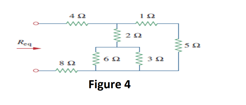
b) Using your formulations in (a), find the current in the Load Resistor
RL of resistance 30Ω and Thevenin’s resistance Rth of Figure 4 below.
c) Find the resistance Req shown in the circuit in Figure 4 below using
your knowledge of parallel and series connections demonstrated in
(a)


Trending now
This is a popular solution!

Step by step
Solved in 2 steps with 4 images


