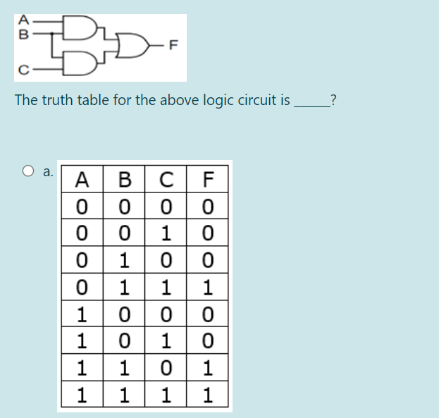
A в -F The truth table for the above logic circuit is ? C F a. A B 0 10 0 0 1 1 0 00 1 1 1 1 1 1 0 1 1 1 1 1


Q: Solve the boolean expression with a truth table and design its logic gate F1(X,Y,Z) =…
A:
Q: 6. Simplify the given expression to its SOP form. Draw the logic circuit for the simplified SOP…
A: SOP stands for sum of product In this all the terms are in sum form and terms can be in product…
Q: For the logic circuit given in figure (1), a) Find the Boolean expression of the circuit output in…
A: The basic logic gates are classified into seven types: AND gate, OR gate, XOR gate, NAND gate, NOR…
Q: The logic circuit shown can be minimized to *
A:
Q: Write the Boolean expression of .1 :the following logic circuits Exclusive-OR A B Exclusive-NOR AB…
A:
Q: Use Boolean algebra to simplify the following expression, then draw a logic gate circuit for the…
A: Given a Boolean Expression Below is the simplified form of this expression and the logic gate for…
Q: H.W : Design a logic circuit to produce an output F 1 if and only if the input which is represented…
A: Here the greatest number circuit cak detect is 13 So # of input bits required =ceil(log 213) = 4…
Q: Analyze the given truth table to find out the simplified Boolean expression using K-Map SOP method.…
A: Given:
Q: Draw a one stage of logic circuit with the following 6 logic operations: AND, NAND, OR, NOR, X-OR,…
A: I have provided a solution in step2.
Q: Simplify the given Boolean function and design its logic gates F1(x,y,z) = xy’z+xyz+y’z’
A:
Q: Derive the min-terms of the function F(A,B,C,D) realized by the logic circuit shown below. 4x1…
A: Answer :-
Q: Simplify the given Boolean function and design its logic gates. F4(x,y,z) = x’y’+xz+x’z (Hint :…
A:
Q: Identify the corresponding Logic Circuit for the below given Boolean Expression. X= (A OB) (A-C) O…
A: The correct Logic Circuit for X = (A XOR B) AND (A NAND C) is the (C) option.
Q: The following logic circuits consist of two exclusive-OR gates and an inverter. Construct the output…
A: A truth table is a mathematical table used in logic—specifically in connection with Boolean algebra,…
Q: Construct a logic circuit using all of the necessary gates in order to product the output (x +z)(y…
A: The logic circuit that will product the output as - (x + z)(y + z) is given below.
Q: Complete the truth table for the following sequential circuit: Next State A BXA B D Q ко 1 ллл 1 1,…
A: D flip-flop is a data flip-flop which stores only the single bit information. It produces output…
Q: 4.Implement the Boolean function F= xy+x'y'+y'z using AND , OR and NOT gates
A:
Q: a Construct circuits from inverters, AND gates, and OR gates to produce the output (x + yz)(xy + z).
A:
Q: yz 00 01 11 10 1 1 1 1 yz 00 01 11 10 1 1 1 01 1 1. 1.
A:
Q: Q2: A) Apply DeMorgan's theorems for the following expression :- ABCD+E+F+GH B) Draw the logic gates…
A: Demorgan's theorem: (A+B)' = A'B' (AB)' = A'+B' Gates used in expression: A' : Not gate A+B : Or…
Q: The Boolean expression of the logical -3 circuit in figure bellow is D X. AB
A:
Q: The output a of the above logic circuit is
A: A logic gate is an idealized model of computation or physical electronic device implementing a…
Q: rive the logic expressions for a circuit that compares two unsigned numbers: nd Y = y2y1yo and…
A: To compare two unsigned numbers, you need to compare the individual bit positions. Start with the…
Q: yz 00 01 11 10 1 1 1
A:
Q: Problem 3. Simplify the following Boolean algebraic expressions and draw a block diagram of the…
A: As per our guidelines we are supposed to answer only one question in case of multiple questions.…
Q: Simplify the given Boolean function and design its logic gates. F7(x,y,z) = x’yz + xy’z + xyz’ +…
A:
Q: Simplify the given Boolean function and design its logic gates. F5(x,y,z) = xy’z+x’y’z (Hint :…
A: F5(x,y,z) = xy’z + x’y’z = (x+x')y'z [Taking y'z common from both terms]…
Q: Design a circuit that produces a HIGH out when only two out of 3 inputs are the same. Use a truth…
A: Assume that, Input variables A, B, C Output variable Z The circuit must produce 1 when only two out…
Q: 3-Design logic circuit by using a decoder which represents the equation F(A,B) = Z(0,1,2)?
A: Solution:-
Q: Given a = (a + b' + c) (a + b' +c) and B = a +b'.e. Show whether x = A by using the truth table. (a)…
A: (a) Given logic function is, α=(a+b'+c').(a+b'+c) β=a+b'.c The truth table for these functions is:…
Q: Give a logical expression corresponding to the following logic circuit D-DO and draw an equivalent…
A: Let's understand step by step : If Truth Table is made for given problem then it is coming as :…
Q: Simplify the given Boolean function and design its logic gates. F8(x,y,z) = (x+y) (x+z) (y+z)…
A:
Q: Use Boolean algebra to simplify the following expression, then draw a logic gate circuit for the…
A: check the step 2 for solution
Q: Develop a truth table for the circuit shown in Figure1. A в X .D
A: Answer of the given question : here 6 logic gate is used : and 4 signal then total no. of output…
Q: A combinational logic circuit is defined by the following two functions: F1 = ABD + ABC D+ BCD F2 =…
A: A combinational circuit is a circuit where we use different gates like decoder, encoder,…
Q: A combinational circuit has four inputs and one output. The output is equal to 1 high, when (a) all…
A: A Boolean expression is a logical statement that is either TRUE or FALSE. The table used to…
Q: Use Boolean algebra to simplify the following expression, then draw a logic gate circuit for the…
A: Given Boolean expression is, A(B+AB)+AC =AB+AAB+AC =AB+AB+AC where aa=a =AB+AC where a+a=a =A(B+C)…
Q: rite the minimized output Y for the logic circuit shown:
A: (((A+B)'.C'+(ABC))'®D)' ((((A+B)'.C')'.(ABC)')®D)' ((A+B+C).(ABC)'®D)' (ABC®D)' (ABC)'D+(ABC)D' ®…
Q: sy using the Karnaugh map method, design a logic circuit with an ing BCD) and one output (Y). The…
A: Groups (0,1,2,3)A'.B'
Q: Simplify the given Boolean function and design its logic gates. F6(x,y,z) = x+y’z (Hint : x.x’ = 0…
A:
Q: A O В -F D O
A:
Q: Using LogicWorks to design a circuit that impalement the following function with NAND gates only…
A: STEPS: First we will see the expression from the truth table and then we will minimize the circuit…
Q: WRITE THE LOGIC EQUATION CONTRUCT THE TRUTH TABLE OGIC CIRCUIT (A)
A:
Q: The following logic circuit has four inputs A, B, C, and D. Write the Boolean expression for X.…
A: Given the logic circuit we have to write the Boolean Expression of A, B, C and D for the final…
Q: for this boolean expression X(YZ'+Y'Z) draw the logic circuit.
A: logic circuit for this boolean expression is given below
Q: Given the Boolean function: F = xy' + z'y'z + xyz e. Draw the logic diagram from the simplified…
A: Given F = xy' + z'y'z + xyz The total number of gates required to implement this equation are 4 (3…
Q: Use Boolean algebra to simplify the following expression, then draw a logic gate circuit for the…
A:
Q: Translate the given expression into its equivalent logic gate circuit: C (A + B) DE
A: We have to create and logic between C and (A+b) after that create and gate for DE and after…
Q: Develop a logic circuit that will produce a 1 on its output only when all three inputs are 1s or…
A:
Q: Simplify the given Boolean function and design its logic gates. F9(x,y,z) = x’y+yz (Hint : x.x’ =…
A:

Step by step
Solved in 2 steps with 1 images


- In the 3-bit counter circuit shown in the figure, the initial value of the output is set to Y = Y2Y1Yo = 111. What is the value of the output Y after 3 hours mark?Identify the state diagram operation and find its output sequence for the following input sequence X=0101-1100-101-0000 the circuit accepts input bits from LSB to MSB(a) Perform the following binary additions. (i) 110111 + 11010 (ii) 101101.101 + 101011.011 (iii) 1101101.101 + 110110.01 (b) Design a logic circuit that allows a signal to pass to the output only when one, but not both, of the control inputs are HIGH; otherwise, the output will stay HIGH.
- Design a logic circuit to implement the operation specified in the truth table given below. Truth table INPUT Output Product Term ABC X 000 001 010 011 100 101 110 111 0 0 0 1 0 1 1 0 A’BCAB’C ABC’The digital logic family which has the lowest propagation delay time is (A) ECL(B) TTL(C) CMOS(D) PMOSF =A'BC'+A'CD'+ACD+AB'C'D' Draw the Logic Gates diagram please Need Asap
- The counting sequence of a 3-bit synchronous counter using JK flip-flops is as follows: 3, 5, 2, 7, 1, 4, 3Implement the counter using JK flip-flops.Design a combinational logic circuit that takes a 3–bit input and has one output P. The P output should be active high only when the inputs corresponds to a prime number Note: the prime numbers: Prime numbers are 2, 3, 5, 7… Select one: a. P= AC+B b. P= A'C+A'B c. P= AC+A'B d. P= AC+A'B'Draw the 1-bit ALU circuit by designing the logic processor part of ALU which performs the operations described in the table.
- Design a four-bit counter that goes through the sequence: x+1→x+2→x+3→x+4→x+5 SolveX = 7Then Solve X = 9design and implement a combinational logic circuit that adds binary numbers and acircuit that will multiply a 2-bit number by a 2-bit numberDesign a sequential circuit that detects the serial input sequence of '10010'. And implement the circuit on software.