a) When the output voltage of a static CMOS inverter just begins the transition from a high output voltage to a low output voltage, it is likely the PMOS device is in the saturation region and the NMOS device is in triode. b) The primary reason NMOS resistively loaded logic is undesired for modern applications relates to the fact that VoL does not come all the way down to ground (zero volts). c) A p-type MOS capacitor has a positive voltage bias applied from the metal side of the oxide to the p-type semiconductor, and the voltage is above the flatband voltage (VFB), the capacitor is in “inversion".
a) When the output voltage of a static CMOS inverter just begins the transition from a high output voltage to a low output voltage, it is likely the PMOS device is in the saturation region and the NMOS device is in triode. b) The primary reason NMOS resistively loaded logic is undesired for modern applications relates to the fact that VoL does not come all the way down to ground (zero volts). c) A p-type MOS capacitor has a positive voltage bias applied from the metal side of the oxide to the p-type semiconductor, and the voltage is above the flatband voltage (VFB), the capacitor is in “inversion".

Introductory Circuit Analysis (13th Edition)
13th Edition
ISBN:9780133923605
Author:Robert L. Boylestad
Publisher:Robert L. Boylestad
Chapter1: Introduction
Section: Chapter Questions
Problem 1P: Visit your local library (at school or home) and describe the extent to which it provides literature...

Related questions

Question
Determine weather it's true or false ?
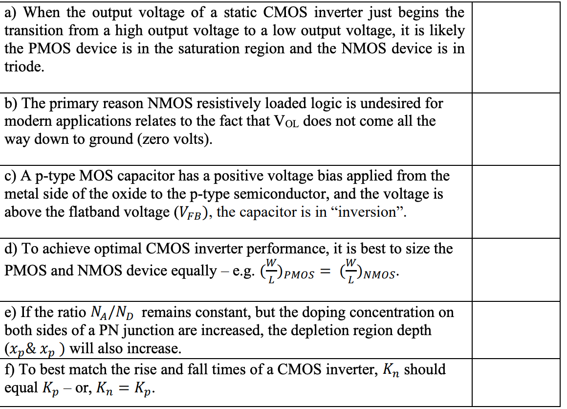
Transcribed Image Text:a) When the output voltage of a static CMOS inverter just begins the
transition from a high output voltage to a low output voltage, it is likely
the PMOS device is in the saturation region and the NMOS device is in
triode.
b) The primary reason NMOS resistively loaded logic is undesired for
modern applications relates to the fact that VOL does not come all the
way down to ground (zero volts).
c) A p-type MOS capacitor has a positive voltage bias applied from the
metal side of the oxide to the p-type semiconductor, and the voltage is
above the flatband voltage (VFB), the capacitor is in “inversion".
d) To achieve optimal CMOS inverter performance, it is best to size the
PMOS and NMOS device equally – e.g. ()PMos = G)nmos-
W
e) If the ratio NA/ND remains constant, but the doping concentration on
both sides of a PN junction are increased, the depletion region depth
(Xp& Xp ) will also increase.
f) To best match the rise and fall times of a CMOS inverter, Kn should
equal Kp – or, Kn = Kp.
Expert Solution
This question has been solved!
Explore an expertly crafted, step-by-step solution for a thorough understanding of key concepts.

Step by step
Solved in 2 steps

Knowledge Booster


Learn more about
Need a deep-dive on the concept behind this application? Look no further. Learn more about this topic, electrical-engineering and related others by exploring similar questions and additional content below.Recommended textbooks for you
Introductory Circuit Analysis (13th Edition)
Electrical Engineering
ISBN:
9780133923605
Author:
Robert L. Boylestad
Publisher:
PEARSON

Delmar's Standard Textbook Of Electricity
Electrical Engineering
ISBN:
9781337900348
Author:
Stephen L. Herman
Publisher:
Cengage Learning

Programmable Logic Controllers
Electrical Engineering
ISBN:
9780073373843
Author:
Frank D. Petruzella
Publisher:
McGraw-Hill Education
Introductory Circuit Analysis (13th Edition)
Electrical Engineering
ISBN:
9780133923605
Author:
Robert L. Boylestad
Publisher:
PEARSON
Delmar's Standard Textbook Of Electricity
Electrical Engineering
ISBN:
9781337900348
Author:
Stephen L. Herman
Publisher:
Cengage Learning
Programmable Logic Controllers
Electrical Engineering
ISBN:
9780073373843
Author:
Frank D. Petruzella
Publisher:
McGraw-Hill Education

Fundamentals of Electric Circuits
Electrical Engineering
ISBN:
9780078028229
Author:
Charles K Alexander, Matthew Sadiku
Publisher:
McGraw-Hill Education

Electric Circuits. (11th Edition)
Electrical Engineering
ISBN:
9780134746968
Author:
James W. Nilsson, Susan Riedel
Publisher:
PEARSON

Engineering Electromagnetics
Electrical Engineering
ISBN:
9780078028151
Author:
Hayt, William H. (william Hart), Jr, BUCK, John A.
Publisher:
Mcgraw-hill Education,