A. Given the per unit equivalent circuit below, solve for V2 in per unit. I P₁=0.8 p.u. PF-0.9 lag V₁=1.0 p.u. ₁ VO 0.03+10.04 0.045+10.06 m P₁=1.2 p.u. PF=0.95 lag V₂
A. Given the per unit equivalent circuit below, solve for V2 in per unit. I P₁=0.8 p.u. PF-0.9 lag V₁=1.0 p.u. ₁ VO 0.03+10.04 0.045+10.06 m P₁=1.2 p.u. PF=0.95 lag V₂

Power System Analysis and Design (MindTap Course List)
6th Edition
ISBN:9781305632134
Author:J. Duncan Glover, Thomas Overbye, Mulukutla S. Sarma
Publisher:J. Duncan Glover, Thomas Overbye, Mulukutla S. Sarma
Chapter2: Fundamentals
Section: Chapter Questions
Problem 2.1P: Given the complex numbers A1=630 and A2=4+j5, (a) convert A1 to rectangular form: (b) convert A2 to...

Related questions
Question
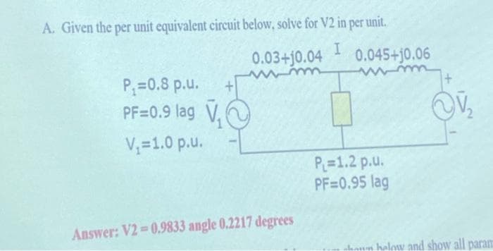
Transcribed Image Text:A. Given the per unit equivalent circuit below, solve for V2 in per unit.
I
P₁=0.8 p.u.
PF=0.9 lag ₁
V₁=1.0 p.u.
0.03+10.04 0.045+10.06
Answer: V2=0.9833 angle 0.2217 degrees
P₁=1.2 p.u.
PF=0.95 lag
~V₂
haun halow and show all param
Expert Solution
This question has been solved!
Explore an expertly crafted, step-by-step solution for a thorough understanding of key concepts.

This is a popular solution!

Trending now
This is a popular solution!

Step by step
Solved in 2 steps with 2 images

Knowledge Booster


Learn more about
Need a deep-dive on the concept behind this application? Look no further. Learn more about this topic, electrical-engineering and related others by exploring similar questions and additional content below.Recommended textbooks for you
Power System Analysis and Design (MindTap Course …
Electrical Engineering
ISBN:
9781305632134
Author:
J. Duncan Glover, Thomas Overbye, Mulukutla S. Sarma
Publisher:
Cengage Learning
Power System Analysis and Design (MindTap Course …
Electrical Engineering
ISBN:
9781305632134
Author:
J. Duncan Glover, Thomas Overbye, Mulukutla S. Sarma
Publisher:
Cengage Learning