a. the temperatures, in °F, of the refrigerant in each evaporator. b. the power input to each compressor stage, in horsepower. c. the overall coefficient of performance.
a. the temperatures, in °F, of the refrigerant in each evaporator. b. the power input to each compressor stage, in horsepower. c. the overall coefficient of performance.

Refrigeration and Air Conditioning Technology (MindTap Course List)
8th Edition
ISBN:9781305578296
Author:John Tomczyk, Eugene Silberstein, Bill Whitman, Bill Johnson
Publisher:John Tomczyk, Eugene Silberstein, Bill Whitman, Bill Johnson
Chapter40: Typical Operating Conditions
Section: Chapter Questions
Problem 2RQ: The typical temperature relationship between a standard-efficiency air-cooled condenser and the...

Related questions
Question
Transcribed Image Text:Oout
Condenser
4
5
We2
Compressor
Expansion
valve
-3
9-
Direct
Evaporator
8.
contact
eat
exchanger
Qin2
= 10 tons
-2
Expansion
Compressor
We.1
valve
+7
Evaporator
Qin. = 5 tons
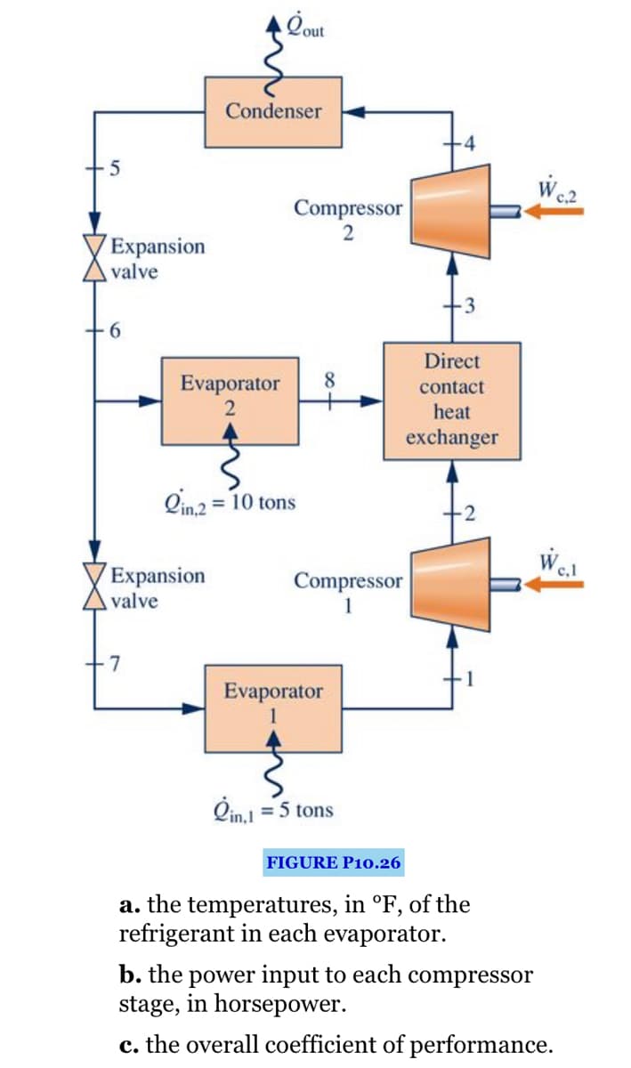
FIGURE P10.26
a. the temperatures, in °F, of the
refrigerant in each evaporator.
b. the power input to each
stage, in horsepower.
compressor
c. the overall coefficient of performance.
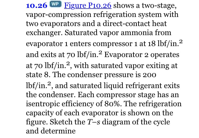
Transcribed Image Text:10.26 WP Figure P10.26 shows a two-stage,
vapor-compression refrigeration system with
two evaporators and a direct-contact heat
exchanger. Saturated vapor ammonia from
evaporator 1 enters compressor 1 at 18 lbf/in.?
and exits at 70 lbf/in.? Evaporator 2 operates
at 70 lbf/in.?, with saturated vapor exiting at
state 8. The condenser pressure is 200
2
Ibf/in.?, and saturated liquid refrigerant exits
the condenser. Each compressor stage has an
isentropic efficiency of 80%. The refrigeration
capacity of each evaporator is shown on the
figure. Sketch the T-s diagram of the cycle
and determine
2
Expert Solution
This question has been solved!
Explore an expertly crafted, step-by-step solution for a thorough understanding of key concepts.

This is a popular solution!

Trending now
This is a popular solution!

Step by step
Solved in 2 steps with 4 images

Recommended textbooks for you
Refrigeration and Air Conditioning Technology (Mi…
Mechanical Engineering
ISBN:
9781305578296
Author:
John Tomczyk, Eugene Silberstein, Bill Whitman, Bill Johnson
Publisher:
Cengage Learning
Refrigeration and Air Conditioning Technology (Mi…
Mechanical Engineering
ISBN:
9781305578296
Author:
John Tomczyk, Eugene Silberstein, Bill Whitman, Bill Johnson
Publisher:
Cengage Learning