An electrical engineering student creates a circuit as shown in the figure Find the following. (Assume c, - 32.0 µF and c, = 3.33 uF.) 6.00 uF C2 µF 9.00 V (a) the equivalent capacitance (in uF) (b) the charge on each capacitor (in uC) C, (left) C1 (right) C2 HC 6.00 µF capacitor HC (c) the potential difference across each capacitor (in V) C, (left) V C, (right) V C2 6.00 µF capacitor V
An electrical engineering student creates a circuit as shown in the figure Find the following. (Assume c, - 32.0 µF and c, = 3.33 uF.) 6.00 uF C2 µF 9.00 V (a) the equivalent capacitance (in uF) (b) the charge on each capacitor (in uC) C, (left) C1 (right) C2 HC 6.00 µF capacitor HC (c) the potential difference across each capacitor (in V) C, (left) V C, (right) V C2 6.00 µF capacitor V

Related questions
Question
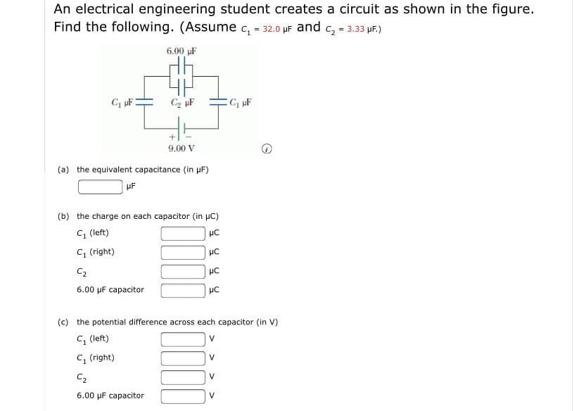
Transcribed Image Text:An electrical engineering student creates a circuit as shown in the figure
Find the following. (Assume c, - 32.0 µF and c, = 3.33 uF.)
6.00 uF
C2 µF
9.00 V
(a) the equivalent capacitance (in uF)
(b) the charge on each capacitor (in uC)
C, (left)
C1 (right)
C2
HC
6.00 µF capacitor
HC
(c) the potential difference across each capacitor (in V)
C, (left)
V
C, (right)
V
C2
6.00 µF capacitor
V
Expert Solution
This question has been solved!
Explore an expertly crafted, step-by-step solution for a thorough understanding of key concepts.

This is a popular solution!

Trending now
This is a popular solution!

Step by step
Solved in 8 steps with 9 images
