Analysis of Trusses by the Method of Joints ● ● Dismember the truss; draw the free-body diagrams of the members and pins. The two forces exerted on each member are equal, have the same line of action, and opposite sense (member forces are either compression or tension). • Forces exerted by a member on the pins or joints at its ends are directed along the member and equal and opposite. ● Method of Joints: successive equilibrium analysis of each joint. ● Conditions of equilibrium on pins provide 2n equations for 2n unknowns. For a simple truss, 2n = m + 3, use to solve for m member forces and 3 reactions at the supports • Conditions for equilibrium for the entire truss provide 3 additional equations which are not independent of the pin equations. Using the method of joints, determine the force in each member of the truss shown below (solve for FAB, FAD, FBD, FDE, FBE, FBC, and FCE. Use the sign convention of negative for compression of the joint and positive for tension of the joint. 2000 lb 1000 lb -12 ft-12 ft. B T 8 ft D 12 ft 6 ft 6 ft Figure 1. Illustration of the problem taken from Vector Mechanics for Engineers: Statics 8th ed. (SI Units) by Beer, Johnston, & Eisenberg Hints: 1. The reaction at the roller support at E is 10,000 lb, upwards. 2. The reaction of the support at C is 7,000 lb, downwards. Questions on the next page. E
Analysis of Trusses by the Method of Joints ● ● Dismember the truss; draw the free-body diagrams of the members and pins. The two forces exerted on each member are equal, have the same line of action, and opposite sense (member forces are either compression or tension). • Forces exerted by a member on the pins or joints at its ends are directed along the member and equal and opposite. ● Method of Joints: successive equilibrium analysis of each joint. ● Conditions of equilibrium on pins provide 2n equations for 2n unknowns. For a simple truss, 2n = m + 3, use to solve for m member forces and 3 reactions at the supports • Conditions for equilibrium for the entire truss provide 3 additional equations which are not independent of the pin equations. Using the method of joints, determine the force in each member of the truss shown below (solve for FAB, FAD, FBD, FDE, FBE, FBC, and FCE. Use the sign convention of negative for compression of the joint and positive for tension of the joint. 2000 lb 1000 lb -12 ft-12 ft. B T 8 ft D 12 ft 6 ft 6 ft Figure 1. Illustration of the problem taken from Vector Mechanics for Engineers: Statics 8th ed. (SI Units) by Beer, Johnston, & Eisenberg Hints: 1. The reaction at the roller support at E is 10,000 lb, upwards. 2. The reaction of the support at C is 7,000 lb, downwards. Questions on the next page. E

International Edition---engineering Mechanics: Statics, 4th Edition
4th Edition
ISBN:9781305501607
Author:Andrew Pytel And Jaan Kiusalaas
Publisher:Andrew Pytel And Jaan Kiusalaas
Chapter10: Virtual Work And Potential Energy
Section: Chapter Questions
Problem 10.57P: Find the stable equilibrium position of the system described in Prob. 10.56 if m = 2.06 kg.

Related questions
Question
100%
please answer this question
Transcribed Image Text:Analysis of Trusses by the Method of Joints
●
●
Dismember the truss; draw the free-body diagrams of the members and pins.
The two forces exerted on each member are equal, have the same line of action,
and opposite sense (member forces are either compression or tension).
●
Forces exerted by a member on the pins or joints at its ends are directed along
the member and equal and opposite.
●
Method of Joints: successive equilibrium analysis of each joint.
●
Conditions of equilibrium on pins provide 2n equations for 2n unknowns. For a
simple truss, 2n = m + 3, use to solve for m member forces and 3 reactions
at the supports
●
Conditions for equilibrium for the entire truss provide 3 additional equations
which are not independent of the pin equations.
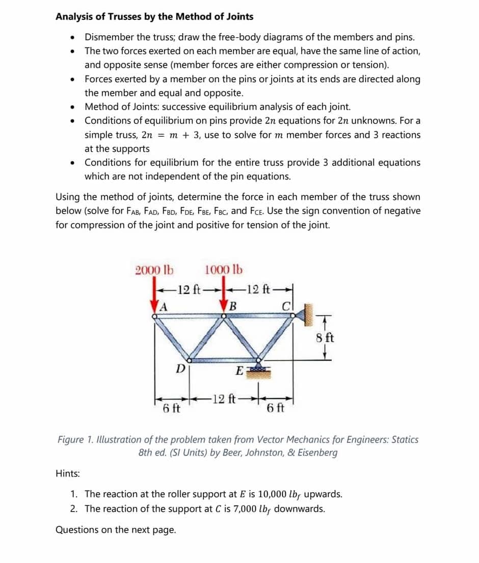
Using the method of joints, determine the force in each member of the truss shown
below (solve for FAB, FAD, FBD, FDE, FBE, FBC, and FCE. Use the sign convention of negative
for compression of the joint and positive for tension of the joint.
2000 lb
1000 lb
12 ft-
A
B
T
8 ft
-12 ft-
6 ft
6 ft
Figure 1. Illustration of the problem taken from Vector Mechanics for Engineers: Statics
8th ed. (SI Units) by Beer, Johnston, & Eisenberg
Hints:
1. The reaction at the roller support at E is 10,000 lb, upwards.
2. The reaction of the support at C is 7,000 lb, downwards.
Questions on the next page.
12 ft-
D
E
Expert Solution
This question has been solved!
Explore an expertly crafted, step-by-step solution for a thorough understanding of key concepts.

This is a popular solution!

Trending now
This is a popular solution!

Step by step
Solved in 2 steps with 3 images

Knowledge Booster


Learn more about
Need a deep-dive on the concept behind this application? Look no further. Learn more about this topic, mechanical-engineering and related others by exploring similar questions and additional content below.Recommended textbooks for you
International Edition---engineering Mechanics: St…
Mechanical Engineering
ISBN:
9781305501607
Author:
Andrew Pytel And Jaan Kiusalaas
Publisher:
CENGAGE L
International Edition---engineering Mechanics: St…
Mechanical Engineering
ISBN:
9781305501607
Author:
Andrew Pytel And Jaan Kiusalaas
Publisher:
CENGAGE L