Analyze and draw the axial, shear, moment diagram and qualitative deflection of each frame. 1. 2 k/ft 30 k E C D Hinge 20 A B 15 ft 15 ft-
Q: DRAW THE SHEAR AND MOMENT DIAGRAMS OF THE FOLLOWING BEAMS AFTER ANALYZING THEM USING THREE MOMENT…
A:
Q: Draw the shear and bending moment diagram and the qualitative deflected shape for the beam shown.
A: Draw the free-body diagram of the beam.
Q: DRAW THE SHEAR AND MOMENT DIAGRAMS OF THE FOLLOWING BEAMS AFTER ANALYZING THEM USING THREE MOMENT…
A:
Q: 3. Using moment-area method, compute the slope and deflection at the free end of the of the…
A: EI = 29000× 122 kft2 × 760124 ft4EI = 153055.56 k.ft2
Q: QUESTION I - TRUSS For the truss shown below, determine the horizontal deflection of joint B by…
A:
Q: Slope-Deflection Equation Calculate the end moments and joint rotations for the continuous beam…
A: Use equation of slope deflection.
Q: The beam shown below is subjected to two 4 kN concentrated loads located 1.5 meters from each…
A:
Q: Calculate the deflection at point C by using Unit Load Method for the beam below
A: NOTE : Since you have asked multiple questions, we will solve the first question for you. If you…
Q: Draw the shear force and bending moment diagrams and sketch the qualitative deflected shape.
A: The figure given in the question are as follows: w=1.5 klf
Q: Use Virtual Work (Unit Load Method) to determine the vertical deflection at Point B for the…
A: Data Given: Asked: Vertical deflection at B
Q: 35 kN 22 kN/m 55 kN–m A B -3 m 9 m 3 m f.
A:
Q: Q1) Derive the equations for slope and deflection of the following beam systems and using the…
A:
Q: Write the shear and moment Equation as function of x of the beam shown below. 100 N 150 N 3 m -3 m A…
A: Given beam is in equillibrium∑Fx=0, HA=0∑Fy=0, RA+RB=100+150=250 ..............(1)∑MA=0,…
Q: Write the equations for moment as a function of distance x along the longitudinal axis of the beam…
A:
Q: Area Moment Method For the given cantilever beam, (a) Compute the rotation at the free end A, in…
A:
Q: 3. Draw the shear and moment diagrams of the beams loaded as shown in the figure below and calculate…
A: Given data: E=150 GPaE=150×106 kPaI=80×106 mm4I=80×10-6 m4EI=80×10-6 ×150×106EI=12000 kN.m2
Q: Determine the Maximum Shear Force (in Ib) using 3 Moment Equation for the Continuous Beam shown in…
A:
Q: 15 kN/m 40 kN 10 kN/m 1m 1m 3m 4m 5m
A: Slope deflection equation is used to determine the slope and subsequently the deflection of a…
Q: Find the moment at support B for the beam shown below using the Slope Deflection Method. Assume B…
A: Given:- From the given question it is required to calculate the moment at support B by using slope…
Q: Use the moment-area method to determine the slope at point A and the deflection at point C of the…
A: Solution;
Q: 15m 2KN/m 15m El-Constant Analyze the beam using Moment Distribution Method Draw shear, bending…
A:
Q: For the following beam, determine: • Deflection of Points B, and E. • Rotation of points A, C, D,…
A: Step 1
Q: Determine the beam deflection at point B. Assume that E = 27700 ksi and / = 718 in.4 are constant.…
A: Option (D) is the correct answer. Using virtual work method.
Q: Analyze and draw the axial, shear, moment diagram and qualitative deflection of each frame. 1. 2…
A: An analytical tool designed to help with structural design is the shear and bending moment diagram,…
Q: 8 k 1.5 k/ft 40 k-ft A B 10 ft - 30 ft -10 ft-
A: Finding out SFD and BMD.
Q: 3. Draw the shear and moment diagrams of the beams loaded as shown in the figure below and calculate…
A: Given: A fixed beam Required: Shear and moment diagram and deflection at 3 m from left support
Q: 1) Find the smallest W section that carries the applied shear load. 2) Find the smallest W section…
A: Given:- Distributed load = 280 KN/m2 Allowable deflection =L240 Fy=345 MPa Span = 5 m Width, bt =…
Q: Use the moment-area method to determine the slopes and deflections at points B and D of the beam…
A: Deflection of a beam: The deflection at any point on the axis of the beam is the distance between…
Q: 0.7L 0.3L P A В
A:
Q: Write the equations for moment as a function of distance x along the longitudinal axis of the beam…
A:
Q: Determine the slope and deflection at point B of the beam shown by the moment-area method. 2 k/ft 1.…
A:
Q: Write the equations for shear and moment using the origins shown in the figure. Evaluate the shear…
A: A beam is load-carrying component of the building which is used to resist seismic conditions and…
Q: Using the Moment Area method, determine the deflection at the right side of t the cantilever beam…
A: P = 60,000lb = 60Klb uniform load between C to D = W Klb/feet E = 29,000ksi I = 4000 in4
Q: Determine the deflection at point B given the cross-section of the beam and assuming E = 200 GPa. A…
A:
Q: determine the rotation and vertical deflection at point C for the beam shown in Figure(1). 6 kips C…
A:
Q: Draw the shear and moments diagrams of the beam shown below using slope-deflection method. 3 k/ft A…
A:
Q: Determine the deflection at point B using slope-deflection equation. Draw the shear and bending…
A: Co
Q: 10 kN/m 5 kN B 6 m
A: The moment-area method is generally used to determine the bending displacement in beams and frames.…
Q: P= 30 kips 12' B 12' P8.13
A: Given data:
Q: 6. Determine the slope at point C of the frame shown in the figure. The support A is fixed. Take E-…
A: To find slope at C
Q: Determine the deflection at point B given the cross-section of the beam and assuming E = 200 GPa. A…
A:
Q: MA = 12 kN. m w = 3 kN/m В 6 m
A:
Q: Analyze and draw the axial, shear, moment diagram and qualitative deflection of each frame. 20 kN 10…
A: To draw sfd, bmd, axial force diagrams, we need to find member forces in each member. To find member…
Q: QUESTION I-TRUSS [40] For the truss shown below, determine the horizontal deflection of joint B by…
A:
Q: w = 12 kips/ft 6 kips D hinge
A:
Q: 12 kips 10 ft 6 ft B D00. 3 kips/ft 16 ft
A: Finding out bending moment diagram and shear force diagram.
Q: Draw the shear and moment diagrams of the beams loaded as shown in the figure below and calculate…
A:
Q: Shear and moment diagrams The deflected shape And locate and give the value of maximum positive…
A:
Q: Using Moment Distribution Method, Analyze the statically Indeterminate Beam shown and Draw the shear…
A: Draw SFD and BMD
Q: a) Analyse the beam above using either the slope-deflection method or the moment distribution…
A:
Please show complete solution, 100% thumbs up GUARANTEE
THEORY OF STRUCTURE (Analysis of Statically Determinate Frames)
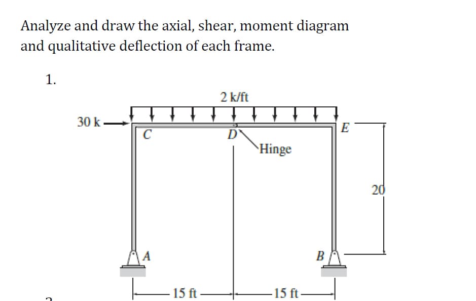
Trending now
This is a popular solution!
Step by step
Solved in 2 steps with 7 images
- Draw the shear and bending momentdiagrams and the qualitative deflected shape for the beamshown.Compute the slope at point A and deflection at point C of the beam using moment-area method. If L = 6ft, w= 1.5k/ft, I=76.8 in4, and E= 29,000 ksi.Using Moment-Area Method, determine the slope at A and B and the deflection at point B of the loaded beam shown. Use E = 150 GPa and I = 110x106 mm4. (Please show moment diagrams by parts)
- Given (Refer to the pictures): Shear and moment diagram of B2 Requirement: What is the deflection of B2 based on the given references? (KINDLY USE AREA-MOMENT METHOD)find the deflection for B2 (point C TO F) using AMM (Area Moment Diagram)(a) Compute the vertical deflection at C, the horizontal deflection at D and the rotation at A by the virtual work method. (b) If support E moves to the right by 5mm and settles downward by 10mm, compute the additional horizontal deflection at D. Given E=200GPa and I=108mm4 .
- Compute the total net deflection of the simply-supported beam with the following properties listed below. (Include the sign if it is negative) Properties:Length = 11.46 mWidth = 302 mmDepth = 435 mmeccentricity = 96 mmEc = 14,368.22 MPaPrestressing Force = 461 kNUnit weight of concrete = 23.16 kN/m3El-ConstantAnalyze the beam using Moment Distribution MethodDraw shear, bending moment and elastic diagramsDetermine the slope and deflection at point B of the beam shown if the figure. Let e= 29 106 ??? and i= 800??4
- Find the end moments for the continuous beam shown using Moment Distribution Method E= 15GPA Diameter of circle= 300mm I at AB= 2 I at BC= 3 I at CD= 4Tabulate the value of deflection of the beam at an interval of 0.2m from the left support and using this values draw the elastic curve of the beam.Determine the deflection at point C. Use the following parameters: P = 40 kips, w = 3.7 kips/ft, E = 29000 ksi, I = 2700 in4 Answer: -0.664