Analyze the bar forces in the trusses shown: Note: Bars 1-3 and 6-7 both make an angle of 30° with the horizontal. 15 90 10 kips 90° 6. 15 10 kips 10 kips 7. 30° -15'- 15'- - 15' 15-


Q: Identify the zero-force member in the truss shown 600 N (a) CD (b) ВЕ (c) вс 2 m (d) CE 900 N E 2 m…
A: In the truss if at a joint only two members are joined and there is no external force at the joint…
Q: 10kN/m 25kN.m 1m 1m Зт 2m
A: Given:- a beam is loaded as shown below
Q: SITUATION. Consider the space truss shown below: 30% Zoom image Determine the force in member AD. B…
A:
Q: The beam shown in Fig. is made from two boards. Draw the shear stress at (A.B.C.D) to hold the…
A:
Q: 201 3-103. The system of four forces acts on the roof truss. Determine the equivalent resultant…
A: Above given truss we have to find the resultant and its position on AB
Q: Identify the zero-force member in the truss shown 600N (a) CD (b) BE (c) BC (d) CE 2m 900 N 2m
A: Given data in question Horizontal loading Dimensions To find out Zero force member
Q: 000 2-46. Determine the x and y components of each force acting on the gusset plate of the bridge…
A:
Q: The beam shown in Fig. is made from two boards. Draw the shear stress at (A.B.C.D) to hold the…
A: Reaction calculation For equilibrium of static (i)∑ME = 0 (ccw +ve, cw -ve) (RE x 8) - [6.5 x 4 x…
Q: 3 m 000 000 4 m A В 000 O 00 The maximum allowable force for members in the truss shown is: 6kN for…
A:
Q: Find the value of Ely at the position midway between the supports. 600 N/m B A D 2m 3m 1m
A:
Q: PROBLEM 3. Determine the force in bars BD, CD, and DF of the Nacelle truss shown below. 600b 1200lb…
A:
Q: 60° F=3 kN 30% C 3 m 60° D 12 m Figure not to scale Figure 1A: Truss viewed in the xy plane. Member…
A:
Q: 1. Determine the magnitude and type of force in each member of the truss shown by the method of…
A: Determine the magnitude and type of force in each member of the truss shown by the method of joints.
Q: Compute the forces in hars AB, AC, DF and DE in the scissors truss shown below: 12 kips F 12 Kips B…
A: Compute the forces in bars AB, AC, DF and DE in the scissors truss shown below:
Q: Analyze the given truss
A: For analyzing given truss, Summation of all forces at all joint is zero.
Q: Calculate ALL the bar forces of the given truss below: D 35 kN A 4m B 84 kN 3m C 4m
A:
Q: Compute the bar forces in the lettered bars of the truss shown. P Ja 45° 45°
A:
Q: Determine the forces in all bars of the trusses. Indicate tension or compression.
A: A rigid body is a body that does not flex or deform under load. The truss is one of the best…
Q: PROBLEM 1 Using Method of Sections, determine the forces in bars BC, HG, and BG for the truss in…
A: Given:- To find:- Forces in BC, HG and BG
Q: 35° 1200 N The truss shown is pin at A and roller at G. a) Solve for the force members: DJ, CI, DI H…
A:
Q: The diagonal members in the center panels of the truss shown are very slender and can act only in…
A: Consider the free body diagram of the truss shown below. Consider the equilibrium moment about F.…
Q: EXTERNALLY INDETERMINATE TRUS 25KN 4m B 15KN 4m A D
A: Given externally indeterminate truss which means that all reactions cant be known by summation of…
Q: For the truss shown below, determine the vertical deflection at joint B. Show all steps clearly.
A: Question is based on the truss supported on the hinge and roller support . Loading condition on…
Q: 416KN 416RN tc 416RN 416RN 416KN 3.5m 2081eN 208RN 4m 4m 4m 4m 4m e
A: The given data is: Load at joint A and G = 208 kN Load at joint B, C, D, E and F = 416 kN
Q: 3. Find the force in the member RP of the frame shown below 500 N a 707.IN b. 500N c. 505N d. 784N 2…
A: Free Body Diagram of the given problem:
Q: Problem 4 For the cantilever truss shown, determine the forces in members DF,FH, GI and FG 40' 24'…
A: cut x-x section moment about I = 0Ffh Cosθ x 24 +FfhSinθ x 20 = 400 x 20 +400 x…
Q: Problem #2: Determine the forces acting in members FE, EB and BC of the truss use the method of…
A:
Q: Calculate the 02, U2, D4 frames axial forces of the given truss system.
A: Load = (4+5) t = 9 t ∑MA=09×2 + 9×6 + 4×10 - RD×12 = 0RD=9.33 t…
Q: 3-5. A sign is subjected to a wind loading that exerts horizontal forces of 300 lb on joints B and C…
A:
Q: 3. Use the method of joints to solve for each of the bar forces of the truss shown. -6m 12 kN 24 kN…
A: The given truss is shown below:
Q: 4. Given: A truss shown below Find: Forces at members CD, CG and GH 80 kN 80 kN В D 3 m A| H G Fooo…
A: Given that: A truss as shown -
Q: Determine the axial forces, shears, and bending moments at points A and B of the structure shown. 1.…
A: Consider the figure,
Q: 5.7. Use the method of joints to detemine the force in each member of the truss shown. State whether…
A: The given truss analyzed by using the equation of equilibrium forces. The algebraic sum of the…
Q: Determine the forces in all bars of the trusses. Indicate tension or compression.
A: The given figure is shown below:
Q: or the given truss system shown, determine ne following. Pi = 8kN and P2 = 12kN %3D F E 2 m B D 1 m-…
A: To find force in member FB ,EB
Q: Calculate ALL the bar forces of the given truss below: 35 kN 4m 84 kN 4m t3m
A:
Q: Determine the forces in DF, EF, and EG in the truss shown diagrammatically in the figure. 40 kN 40…
A:
Q: Locate the center of gravity of the plane truss shown if all bars have the same weight per unit…
A: A truss is a get-together of straight individuals associated at joints. No part is constant through…
Q: 1. Calculate the force on members X,Y, and Z of the truss by method of sections or joints. Assume…
A:
Q: 5. Given: A truss shown below Find: Forces at members CD, CJ and GJ 15.5 kN 6 kN 9 kN 4 kN 6 kN 2 m…
A:
Q: Truss: Number of member%3D8 Number of support%3D4 Number of joint%3D6 Determine degree of static…
A: Introduction : The given question is related with structural analysis . With help of the data given…
Q: 41-100. For the truss shown, find the stresses or the internal force acting on the members cut by…
A: Consider the figure, Here, T is the tension and C is the compression.
Q: Use the substitute member to make a complete analysis of the complex truss shown. d 3m 25kN - 4 m…
A:
Q: 1. Analyze the beam shown at section 1 (determine the internal force; moment and shear). 500 kn 36…
A:
Q: 35° 1200 N The truss shown is pin at A and roller at G. a) Solve for the force members: DJ, CI, DI…
A:
Q: draw the normal force, cutting force and bending moment diagrams 12 kN/m 8.5 AN 15 6m |+ 2 m
A:
Q: 15 KN 30 kN/m 15 m 15m
A: We have to find the value of bending moment in every portion of the beam:-
Q: Using an approximate analysis of the shown Vierendeel truss, draw the N.F.D., S.F.D. and B.M.D. 40…
A:
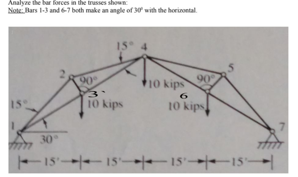
Analyze the bar forces in the trusses shown:
Note: Bars 1-3 and 6-7 both make an angle of 30° with the horizontal.

Step by step
Solved in 2 steps with 1 images

- Help please 3 decimal places. and box the final answer. Please dont make it complicated Determine the resultant R of the Four forces acting on the simple truss. The Fourth force is acting on the node where the 25 KN is at and is directed upward with a magnitude of 15 KN. Specify the points on the x- and y-axes through which R must pass.(image attached) 1. Find the force in members AB, BC, BD and CD. 2. Find the absolute vertical displacement of joint C (in inches). Use principal of virtual work. Given: EA= 2000 k for members AB, BC and BD. EA= 4000 k for member CD alpha = 5.0 x 10^-5 degrees Fahrenheit (for all trusses). 6. Does the vertical displacement of C move up or down?Beam ABC is supported by a three-bar truss at point C and at A by an elastomeric pad that is equivalent to a roller. Compute the vertical deflection of point B and the change in length of member DE due to the applied load. Given: E = 29,000 kips/in.2, area of all truss bars = 1 in.2, area of beam = 16 in.2, I of beam = 1200 in.4. Use virtual work method.
- Gate AB in fig.4 is a quarter of circle 6m wide into the paper. Find the force Fjust sufficient to prevent rotation about hinge B. Neglect the weight of the gate.Two forces of 80N and 70N act simultaneously at point. Find the resultant force if the angle between them is 150Find the location of the centroid of the built up section (X̄ , Ȳ) composed of a C380x74 channelwelded to a W360x122 I-beam. Calculate the moment of inertia (second moment of area) of the builtup beam about both its centroidal axes.
- what are the support reactions for points "A" and "B": L=650 cm H=475 cm E=25 GPa P=30 KN Section=15x40 cm q=38 KN/mPlease read and follow the direction. Solve only Beam 3.*(26-27): An isocles triangular plate of height 460 mm and base of 200 mm is submerged vertically in a water with its vertex at the liquid surface and the base is parallel to the liquid surface. 26. Calculate the total force acting on one side of the plate in KN? b.) 115.70 c.) 127.14 a.) 150.68 d.) 138.39 27. Locate the total force from the center of gravity of the plate. a.) 27.62 mm c.) 22.4 mm d) 38.33 mm b.) 40 mm
- Calculate the forces at the points with movement restrictions imposed. Data: L1 = 1.9m L2 = 3.3m L3 = 3.5m q1 = 65kN/m M1 = 189kNmA 140 KN force with a slope of 4 vertical and 7 horizontal islocated on the second quadrant. Determine its y- component.a. 121.55 KNb. 69.46 KNc. 112.55 KNd. 96.46 KNA resultant force of 8kN is required to act on the plate shown in the figure. The resultant force should be directed 30° above the x-axis. If F1 = 5kN and F3 = 4kN (slope= 2:3), determine the magnitude of F2 and the angle it makes with the x-axis.