and 50, respectively. The data inputs 10 through 17 are as follows: 1) An 8-1 multiplexer has inputs A, B, and C connected to the selection inputs 52, 51, 10-D, 11-1; 12-0, 13-D; 14-D, IS-D; 16-0, 17-1; a) Fill the following truth table according to the given information b) Determine the Boolean function that is implemented by the multiplexer in the canonical SOP form. e) Simplify the function using Karnaugh Map and find the shortest possible expression. d) Draw the circuit showing all the inputs and output, using AND, OR, NOT gates. A B CD F F A, B C, D 00 01 11 10 0.0 01 11 10 Cave
and 50, respectively. The data inputs 10 through 17 are as follows: 1) An 8-1 multiplexer has inputs A, B, and C connected to the selection inputs 52, 51, 10-D, 11-1; 12-0, 13-D; 14-D, IS-D; 16-0, 17-1; a) Fill the following truth table according to the given information b) Determine the Boolean function that is implemented by the multiplexer in the canonical SOP form. e) Simplify the function using Karnaugh Map and find the shortest possible expression. d) Draw the circuit showing all the inputs and output, using AND, OR, NOT gates. A B CD F F A, B C, D 00 01 11 10 0.0 01 11 10 Cave

Introductory Circuit Analysis (13th Edition)
13th Edition
ISBN:9780133923605
Author:Robert L. Boylestad
Publisher:Robert L. Boylestad
Chapter1: Introduction
Section: Chapter Questions
Problem 1P: Visit your local library (at school or home) and describe the extent to which it provides literature...

Related questions
Question
please solve part d ony
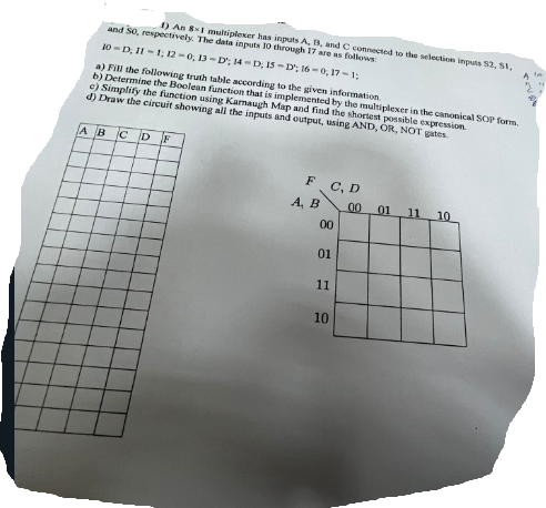
Transcribed Image Text:and 50, respectively. The data inputs 10 through 17 are as follows:
1) An 8-1 multiplexer has inputs A, B, and C connected to the selection inputs 52, 51,
10-D, 11-1; 12-0, 13-D; 14-D, IS-D; 16-0, 17-1;
a) Fill the following truth table according to the given information
b) Determine the Boolean function that is implemented by the multiplexer in the canonical SOP form.
e) Simplify the function using Karnaugh Map and find the shortest possible expression.
d) Draw the circuit showing all the inputs and output, using AND, OR, NOT gates.
A B
CD F
F
A, B
C, D
00
01
11
10
0.0 01 11 10
Cave
Expert Solution
This question has been solved!
Explore an expertly crafted, step-by-step solution for a thorough understanding of key concepts.

This is a popular solution!

Trending now
This is a popular solution!

Step by step
Solved in 4 steps with 4 images

Knowledge Booster


Learn more about
Need a deep-dive on the concept behind this application? Look no further. Learn more about this topic, electrical-engineering and related others by exploring similar questions and additional content below.Recommended textbooks for you
Introductory Circuit Analysis (13th Edition)
Electrical Engineering
ISBN:
9780133923605
Author:
Robert L. Boylestad
Publisher:
PEARSON

Delmar's Standard Textbook Of Electricity
Electrical Engineering
ISBN:
9781337900348
Author:
Stephen L. Herman
Publisher:
Cengage Learning

Programmable Logic Controllers
Electrical Engineering
ISBN:
9780073373843
Author:
Frank D. Petruzella
Publisher:
McGraw-Hill Education
Introductory Circuit Analysis (13th Edition)
Electrical Engineering
ISBN:
9780133923605
Author:
Robert L. Boylestad
Publisher:
PEARSON
Delmar's Standard Textbook Of Electricity
Electrical Engineering
ISBN:
9781337900348
Author:
Stephen L. Herman
Publisher:
Cengage Learning
Programmable Logic Controllers
Electrical Engineering
ISBN:
9780073373843
Author:
Frank D. Petruzella
Publisher:
McGraw-Hill Education

Fundamentals of Electric Circuits
Electrical Engineering
ISBN:
9780078028229
Author:
Charles K Alexander, Matthew Sadiku
Publisher:
McGraw-Hill Education

Electric Circuits. (11th Edition)
Electrical Engineering
ISBN:
9780134746968
Author:
James W. Nilsson, Susan Riedel
Publisher:
PEARSON

Engineering Electromagnetics
Electrical Engineering
ISBN:
9780078028151
Author:
Hayt, William H. (william Hart), Jr, BUCK, John A.
Publisher:
Mcgraw-hill Education,