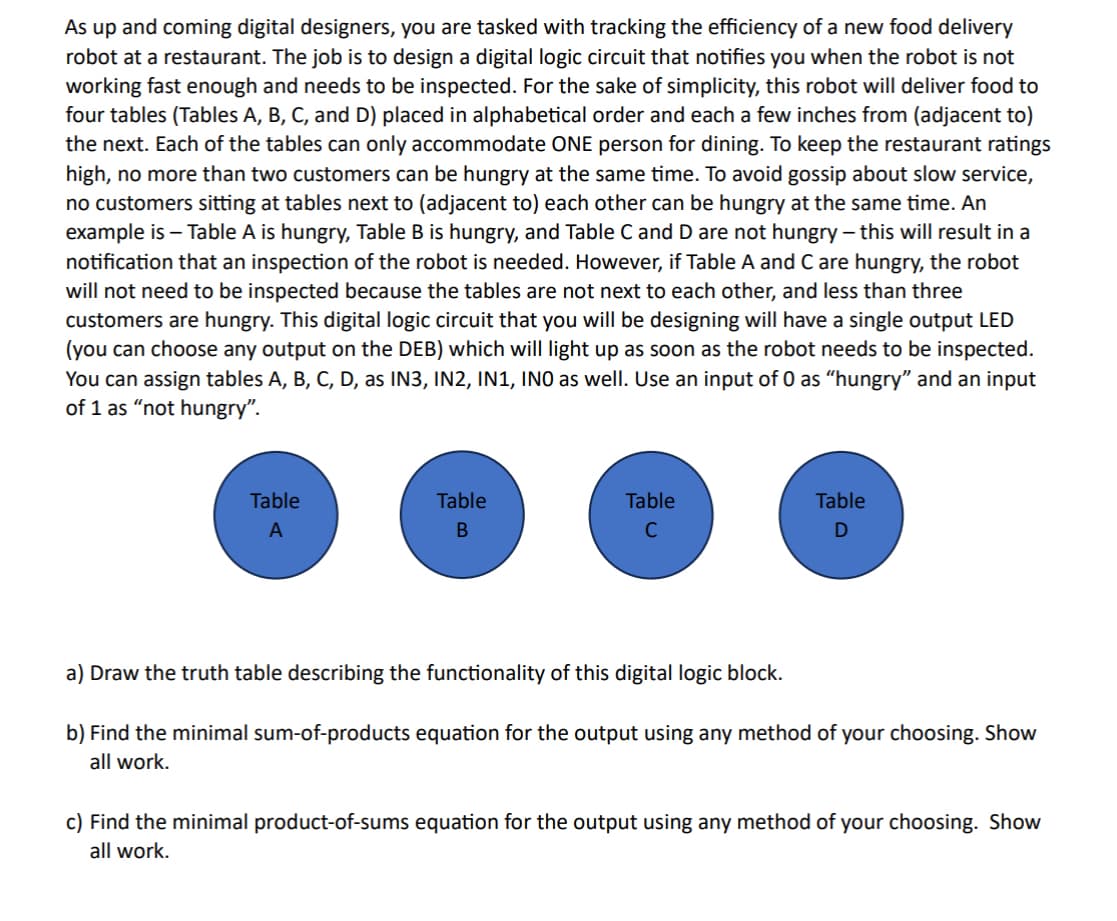
As up and coming digital designers, you are tasked with tracking the efficiency of a new food delivery robot at a restaurant. The job is to design a digital logic circuit that notifies you when the robot is not working fast enough and needs to be inspected. For the sake of simplicity, this robot will deliver food to four tables (Tables A, B, C, and D) placed in alphabetical order and each a few inches from (adjacent to) the next. Each of the tables can only accommodate ONE person for dining. To keep the restaurant ratings high, no more than two customers can be hungry at the same time. To avoid gossip about slow service, no customers sitting at tables next to (adjacent to) each other can be hungry at the same time. An example is - Table A is hungry, Table B is hungry, and Table C and D are not hungry - this will result in a notification that an inspection of the robot is needed. However, if Table A and C are hungry, the robot will not need to be inspected because the tables are not next to each other, and less than three customers are hungry. This digital logic circuit that you will be designing will have a single output LED (you can choose any output on the DEB) which will light up as soon as the robot needs to be inspected. You can assign tables A, B, C, D, as IN3, IN2, IN1, INO as well. Use an input of 0 as "hungry" and an input of 1 as "not hungry". Table A Table B Table C Table D a) Draw the truth table describing the functionality of this digital logic block. b) Find the minimal sum-of-products equation for the output using any method of your choosing. Show all work. c) Find the minimal product-of-sums equation for the output using any method of your choosing. Show all work.
As up and coming digital designers, you are tasked with tracking the efficiency of a new food delivery robot at a restaurant. The job is to design a digital logic circuit that notifies you when the robot is not working fast enough and needs to be inspected. For the sake of simplicity, this robot will deliver food to four tables (Tables A, B, C, and D) placed in alphabetical order and each a few inches from (adjacent to) the next. Each of the tables can only accommodate ONE person for dining. To keep the restaurant ratings high, no more than two customers can be hungry at the same time. To avoid gossip about slow service, no customers sitting at tables next to (adjacent to) each other can be hungry at the same time. An example is - Table A is hungry, Table B is hungry, and Table C and D are not hungry - this will result in a notification that an inspection of the robot is needed. However, if Table A and C are hungry, the robot will not need to be inspected because the tables are not next to each other, and less than three customers are hungry. This digital logic circuit that you will be designing will have a single output LED (you can choose any output on the DEB) which will light up as soon as the robot needs to be inspected. You can assign tables A, B, C, D, as IN3, IN2, IN1, INO as well. Use an input of 0 as "hungry" and an input of 1 as "not hungry". Table A Table B Table C Table D a) Draw the truth table describing the functionality of this digital logic block. b) Find the minimal sum-of-products equation for the output using any method of your choosing. Show all work. c) Find the minimal product-of-sums equation for the output using any method of your choosing. Show all work.

Introductory Circuit Analysis (13th Edition)
13th Edition
ISBN:9780133923605
Author:Robert L. Boylestad
Publisher:Robert L. Boylestad
Chapter1: Introduction
Section: Chapter Questions
Problem 1P: Visit your local library (at school or home) and describe the extent to which it provides literature...

Related questions
Question
Transcribed Image Text:d) Assume that the logic gates used have the same cost and performance metrics per gate. Is there any
design advantage to using the prototype from (b) or (c)? Explain why or why not.
e) Build and demonstrate the circuit that will accomplish the task. If your last name starts with an ODD
letter of the alphabet (i.e. A, C, E, G, I, etc.) your prototype will be of part B. If your last name starts
with an EVEN letter of the alphabet (i.e. B, D, F, H, J, etc.) your prototype will be of part C.
Transcribed Image Text:As up and coming digital designers, you are tasked with tracking the efficiency of a new food delivery
robot at a restaurant. The job is to design a digital logic circuit that notifies you when the robot is not
working fast enough and needs to be inspected. For the sake of simplicity, this robot will deliver food to
four tables (Tables A, B, C, and D) placed in alphabetical order and each a few inches from (adjacent to)
the next. Each of the tables can only accommodate ONE person for dining. To keep the restaurant ratings
high, no more than two customers can be hungry at the same time. To avoid gossip about slow service,
no customers sitting at tables next to (adjacent to) each other can be hungry at the same time. An
example is - Table A is hungry, Table B is hungry, and Table C and D are not hungry - this will result in a
notification that an inspection of the robot is needed. However, if Table A and C are hungry, the robot
will not need to be inspected because the tables are not next to each other, and less than three
customers are hungry. This digital logic circuit that you will be designing will have a single output LED
(you can choose any output on the DEB) which will light up as soon as the robot needs to be inspected.
You can assign tables A, B, C, D, as IN3, IN2, IN1, INO as well. Use an input of 0 as "hungry" and an input
of 1 as "not hungry".
Table
A
Table
Table
C
a) Draw the truth table describing the functionality of this digital logic block.
Table
D
b) Find the minimal sum-of-products equation for the output using any method of your choosing. Show
all work.
c) Find the minimal product-of-sums equation for the output using any method of your choosing. Show
all work.
Expert Solution
This question has been solved!
Explore an expertly crafted, step-by-step solution for a thorough understanding of key concepts.

This is a popular solution!
Step 1: Summarize the given information.
VIEWStep 2: Choosing the input and output variables.
VIEWStep 3: Constructing the truth table.
VIEWStep 4: Constructing the K-map and finding the minimal sum of products equation for the output.
VIEWStep 5: Constructing the K-map and finding the minimal sum of products equation for the output.
VIEWSolution
VIEW
Trending now
This is a popular solution!

Step by step
Solved in 6 steps with 7 images

Knowledge Booster

![Digital Modulation Scheme (Amplitude-Shift Keying [ASK], Phase-Shift Keying [PSK], Frequency-Shift Keying [FSK])](/static/compass_v2/subjects/engineering/electrical-engineering.svg)
Learn more about
Need a deep-dive on the concept behind this application? Look no further. Learn more about this topic, electrical-engineering and related others by exploring similar questions and additional content below.Recommended textbooks for you
Introductory Circuit Analysis (13th Edition)
Electrical Engineering
ISBN:
9780133923605
Author:
Robert L. Boylestad
Publisher:
PEARSON

Delmar's Standard Textbook Of Electricity
Electrical Engineering
ISBN:
9781337900348
Author:
Stephen L. Herman
Publisher:
Cengage Learning

Programmable Logic Controllers
Electrical Engineering
ISBN:
9780073373843
Author:
Frank D. Petruzella
Publisher:
McGraw-Hill Education
Introductory Circuit Analysis (13th Edition)
Electrical Engineering
ISBN:
9780133923605
Author:
Robert L. Boylestad
Publisher:
PEARSON
Delmar's Standard Textbook Of Electricity
Electrical Engineering
ISBN:
9781337900348
Author:
Stephen L. Herman
Publisher:
Cengage Learning
Programmable Logic Controllers
Electrical Engineering
ISBN:
9780073373843
Author:
Frank D. Petruzella
Publisher:
McGraw-Hill Education

Fundamentals of Electric Circuits
Electrical Engineering
ISBN:
9780078028229
Author:
Charles K Alexander, Matthew Sadiku
Publisher:
McGraw-Hill Education

Electric Circuits. (11th Edition)
Electrical Engineering
ISBN:
9780134746968
Author:
James W. Nilsson, Susan Riedel
Publisher:
PEARSON

Engineering Electromagnetics
Electrical Engineering
ISBN:
9780078028151
Author:
Hayt, William H. (william Hart), Jr, BUCK, John A.
Publisher:
Mcgraw-hill Education,