Assigned resistance values: R₁ = 250, R₂ = 50 Q₂ R₂ = 75 Q Table 6.1 Data R₁ R₂ R; Simulated Data -3 Simulated i is-200x103 ₁=200x10³A₂=200x10 ³A i+= 0.2 A Simulated V V₁-30 V V₂ = 30 V V₁=30 V V₂-30 V V |V₁ + V₂ + V₁=0.2A Computed Data Computed V V₁=5 V V₂ = 10 V V₁= 15 V V₁=30 V V- |V₁ + V₂ + V₁ = 30 V P₁ = 1 P₂=2 P;= 3 Computed Power, P P₁ = 6 P₁ + P₂ + P₂ = 6 W P-= Step 6 Simulated i i-= 0.2 A Simulated V V₁ = 30 V |V₂= 25 V V₁= 15 V V₂=70 V Observations 1. What relationship is observed with regards to the voltage across each resistor? 2. Discuss the relationship of the current, voltage, and power of your connected circuit. 3. What is the observed relationship of the electrical parameters in step 6? A
Assigned resistance values: R₁ = 250, R₂ = 50 Q₂ R₂ = 75 Q Table 6.1 Data R₁ R₂ R; Simulated Data -3 Simulated i is-200x103 ₁=200x10³A₂=200x10 ³A i+= 0.2 A Simulated V V₁-30 V V₂ = 30 V V₁=30 V V₂-30 V V |V₁ + V₂ + V₁=0.2A Computed Data Computed V V₁=5 V V₂ = 10 V V₁= 15 V V₁=30 V V- |V₁ + V₂ + V₁ = 30 V P₁ = 1 P₂=2 P;= 3 Computed Power, P P₁ = 6 P₁ + P₂ + P₂ = 6 W P-= Step 6 Simulated i i-= 0.2 A Simulated V V₁ = 30 V |V₂= 25 V V₁= 15 V V₂=70 V Observations 1. What relationship is observed with regards to the voltage across each resistor? 2. Discuss the relationship of the current, voltage, and power of your connected circuit. 3. What is the observed relationship of the electrical parameters in step 6? A

Introductory Circuit Analysis (13th Edition)
13th Edition
ISBN:9780133923605
Author:Robert L. Boylestad
Publisher:Robert L. Boylestad
Chapter1: Introduction
Section: Chapter Questions
Problem 1P: Visit your local library (at school or home) and describe the extent to which it provides literature...

Related questions
Question
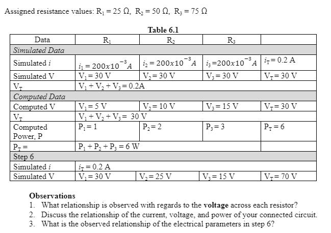
Transcribed Image Text:Assigned resistance values: R₁ = 250, R₂ = 50 0, R₂ = 75 Q
Table 6.1
Data
R₁
R₂
R;3
Simulated Data
Simulated i
-3
₁200x10 A
i₂ = 200x10
i3-200x10³ A = 0.2 A
Simulated V
V₁ = 30 V
V₂ = 30 V
V₂ = 30 V
V₂ = 30 V
V₁
V₁ + V₂ + V₁ = 0.2A
Computed Data
Computed V
V₁=5 V
V₂ = 10 V
V₂ = 15 V
V₁ = 30 V
V₁
V₁ + V₂ + V₂ = 30 V
P₁ = 1
P₂ = 2
Computed
Power, P
P₁ = 3
P₁ = 6
P₁ + P₂ + P₂ = 6 W
P-=
Step 6
Simulated i
i = 0.2 A
Simulated V
V₁ = 30 V
V₂= 25 V
V₁= 15 V
V₂= 70 V
Observations
1. What relationship is observed with regards to the voltage across each resistor?
2. Discuss the relationship of the current, voltage, and power of your connected circuit.
3. What is the observed relationship of the electrical parameters in step 6?
-3
A
Expert Solution
This question has been solved!
Explore an expertly crafted, step-by-step solution for a thorough understanding of key concepts.

Step by step
Solved in 2 steps

Knowledge Booster


Learn more about
Need a deep-dive on the concept behind this application? Look no further. Learn more about this topic, electrical-engineering and related others by exploring similar questions and additional content below.Recommended textbooks for you
Introductory Circuit Analysis (13th Edition)
Electrical Engineering
ISBN:
9780133923605
Author:
Robert L. Boylestad
Publisher:
PEARSON

Delmar's Standard Textbook Of Electricity
Electrical Engineering
ISBN:
9781337900348
Author:
Stephen L. Herman
Publisher:
Cengage Learning

Programmable Logic Controllers
Electrical Engineering
ISBN:
9780073373843
Author:
Frank D. Petruzella
Publisher:
McGraw-Hill Education
Introductory Circuit Analysis (13th Edition)
Electrical Engineering
ISBN:
9780133923605
Author:
Robert L. Boylestad
Publisher:
PEARSON
Delmar's Standard Textbook Of Electricity
Electrical Engineering
ISBN:
9781337900348
Author:
Stephen L. Herman
Publisher:
Cengage Learning
Programmable Logic Controllers
Electrical Engineering
ISBN:
9780073373843
Author:
Frank D. Petruzella
Publisher:
McGraw-Hill Education

Fundamentals of Electric Circuits
Electrical Engineering
ISBN:
9780078028229
Author:
Charles K Alexander, Matthew Sadiku
Publisher:
McGraw-Hill Education

Electric Circuits. (11th Edition)
Electrical Engineering
ISBN:
9780134746968
Author:
James W. Nilsson, Susan Riedel
Publisher:
PEARSON

Engineering Electromagnetics
Electrical Engineering
ISBN:
9780078028151
Author:
Hayt, William H. (william Hart), Jr, BUCK, John A.
Publisher:
Mcgraw-hill Education,