At the shown position, the ground reaction forces measured using a force platform are 600N in the vertical direction (Fy) and 200N in horizontal direction (Fx). The mass of the limb below the knee is 4kg with the centre of gravity at the point G. Determine the forces and moment applied to the knee joint. Draw correct free body diagram using any part of the body shown below. 40cm FX GRF Fy G 8cm 22cm 12cm FX GRF Fy
At the shown position, the ground reaction forces measured using a force platform are 600N in the vertical direction (Fy) and 200N in horizontal direction (Fx). The mass of the limb below the knee is 4kg with the centre of gravity at the point G. Determine the forces and moment applied to the knee joint. Draw correct free body diagram using any part of the body shown below. 40cm FX GRF Fy G 8cm 22cm 12cm FX GRF Fy

International Edition---engineering Mechanics: Statics, 4th Edition
4th Edition
ISBN:9781305501607
Author:Andrew Pytel And Jaan Kiusalaas
Publisher:Andrew Pytel And Jaan Kiusalaas
Chapter5: Three-dimensional Equilibrium
Section: Chapter Questions
Problem 5.19P: The three bars are welded together to form a rigid unit that is supported by three slider bearings....

Related questions
Question
100%
At the shown position, the ground reaction forces measured using a force platform are 600N in the vertical direction (Fy) and 200N in horizontal direction (Fx). The mass of the limb below the knee is 4kg with the centre of gravity at the point G. Determine the forces and moment applied to the knee joint. Draw correct free body diagram using any part of the body shown below.
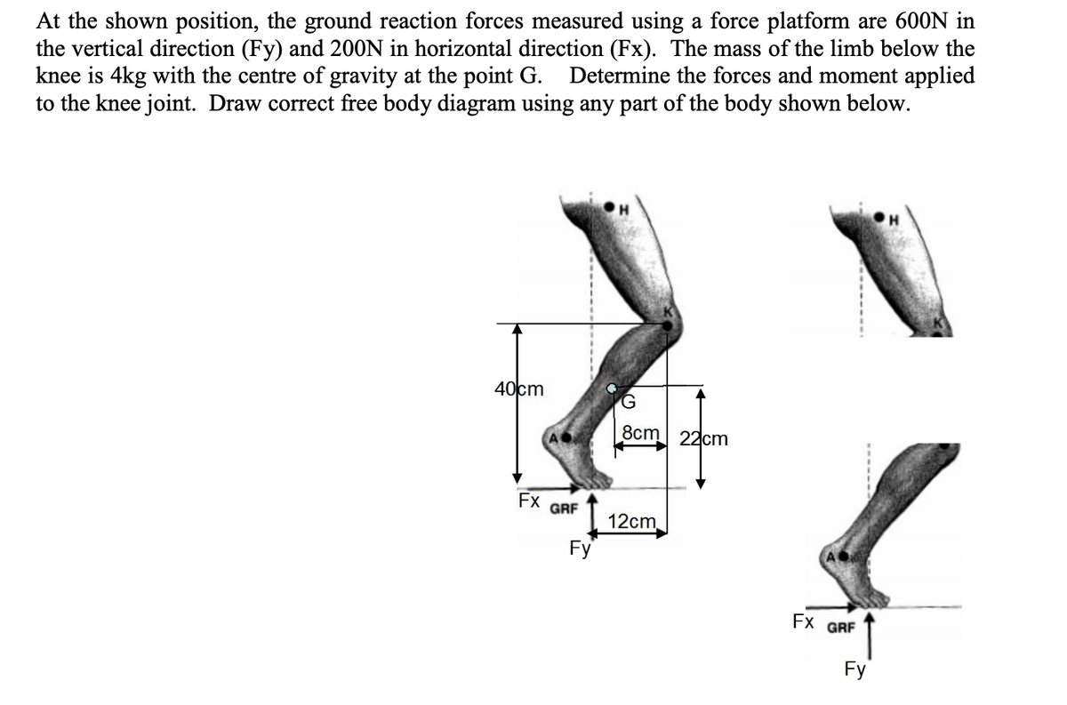
Transcribed Image Text:At the shown position, the ground reaction forces measured using a force platform are 600N in
the vertical direction (Fy) and 200N in horizontal direction (Fx). The mass of the limb below the
knee is 4kg with the centre of gravity at the point G. Determine the forces and moment applied
to the knee joint. Draw correct free body diagram using any part of the body shown below.
40cm
Fx
GRF
Fy
G
8cm
12cm
22cm
Fx GRF
Fy
Expert Solution
This question has been solved!
Explore an expertly crafted, step-by-step solution for a thorough understanding of key concepts.

This is a popular solution!

Trending now
This is a popular solution!

Step by step
Solved in 2 steps with 1 images

Knowledge Booster


Learn more about
Need a deep-dive on the concept behind this application? Look no further. Learn more about this topic, mechanical-engineering and related others by exploring similar questions and additional content below.Recommended textbooks for you
International Edition---engineering Mechanics: St…
Mechanical Engineering
ISBN:
9781305501607
Author:
Andrew Pytel And Jaan Kiusalaas
Publisher:
CENGAGE L
International Edition---engineering Mechanics: St…
Mechanical Engineering
ISBN:
9781305501607
Author:
Andrew Pytel And Jaan Kiusalaas
Publisher:
CENGAGE L