Question
100%
At which times will Q be high?
clk
A) T1, T2, T3, T4
B) T2, T5
C)ll times
C) D) T1 , T3, T4
Ti T23T4T
At which times will Q be high?
clk
OA) T1, T4, T5
B) All times
OC) T2, T3
D) T1, T3, T4, T5
T1 T2 T3T4T
clk
At which times will Q be high?
OA) T3, T5
B) T1, T2, T3
OC) T1, T3, T4, T5
O D) T1, T2, T3, T5
T1
2
T3
T4
Ts
clk
At which times will Q be high?
OA) T4,T5
O B) T2,T
Oc) T2
OD) T2, T4, T5
T1
T2
T3
T4
Ts
expand button
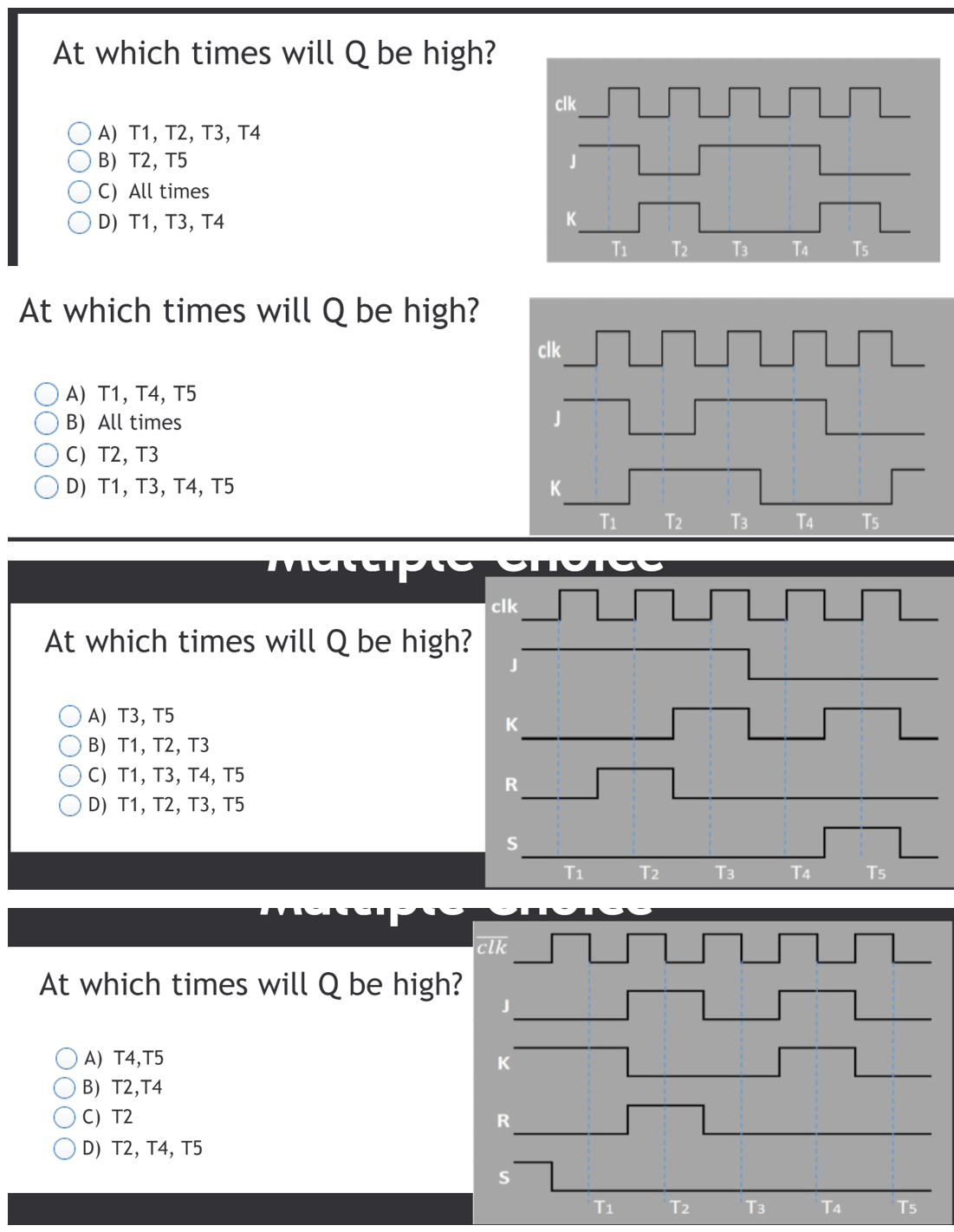
Transcribed Image Text:At which times will Q be high? clk A) T1, T2, T3, T4 B) T2, T5 C)ll times C) D) T1 , T3, T4 Ti T23T4T At which times will Q be high? clk OA) T1, T4, T5 B) All times OC) T2, T3 D) T1, T3, T4, T5 T1 T2 T3T4T clk At which times will Q be high? OA) T3, T5 B) T1, T2, T3 OC) T1, T3, T4, T5 O D) T1, T2, T3, T5 T1 2 T3 T4 Ts clk At which times will Q be high? OA) T4,T5 O B) T2,T Oc) T2 OD) T2, T4, T5 T1 T2 T3 T4 Ts
Expert Solution
Check Mark
Blurred answer
Students who’ve seen this question also like:
Introductory Circuit Analysis (13th Edition)
13th Edition
ISBN: 9780133923605
Author: Robert L. Boylestad
Publisher: PEARSON
Not helpful? See similar books
marketing sidebar icon
Your question is solved by a Subject Matter Expert
marketing sidebar icon
Want to see this answer and more?
Experts are waiting 24/7 to provide step-by-step solutions in as fast as 30 minutes!*
*Response times may vary by subject and question complexity. Median response time is 34 minutes for paid subscribers and may be longer for promotional offers.
Get 24/7 homework help!
8+ million solutions
Get access to millions of step-by-step textbook and homework solutions
Support from experts
Send experts your homework questions or start a chat with a tutor
Essay support
Check for plagiarism and create citations in seconds
Solve math equations
Get instant explanations to difficult math equations
Students love us.
Students love us.

Related Electrical Engineering Q&A

Find answers to questions asked by students like you.

Q: Obtain the expression of the sampled output from the following block diagram: E(s)_ E-(s) U(s) U(s)…

A: Transfer function:             Laplace transform of output divided by Laplace transform of input…

Q: Solve T11(s), T12(s), T21(s) and T22(s). R1 (s) R2 (s) 1 1 G₁ G₂ 11 Y₁ Y2 Y3 -H₁ Y4 Y5 Y6 H₂ -H3 G4…

A: Given: Signal flow graph We have to determine the transfer functions for two different inputs and…

Q: Q1: Consider the experiment of throwing the two fair dice you are then informed that th is not…

A: Click to see the answer

Q: Q.3: Determine the output of DAC in Fig2 if the sequence of 4-bit numbers are applied to the inputs.…

A: An OPAMP(operational amplifier) is an integrated electronic circuit that is used to amplify weak…

Q: -2: A- For the circuit shown, Write an expression for the following: 1- R seen by C2. 2- If we…

A: Click to see the answer

Q: 1. Calculate the expected gains for individual inputs A, D, F to output C, of the circuit shown in…

A: Click to see the answer

Q: Find if memoryless, causal and stable? a) h(t) = u(t+1) – u(t-1) %3D b) h(t) = u(t) – 2u(t-1) %3D c)…

A: Since we are allowed to solve only up to 3 sub parts of a question. The answer contains solution for…

Q: V₁ = 120°, jQG2 =j1.0, Z₁ =j0.5, SD2 =PD2 +j1.0. Find S₁ and V₂. We consider the solution as a…

A: Given V1=1∠0° SD2 =PD2 + j 1 SG2 = 0+ j 1 Z =j 0.5 =0.5 ∠90°

Q: t=0 R1 R2 Vi L1 L2 Vo Find the voltage vo(t) in the s-domain Vo(s). V1 = 100 volts L1 = 152 uH R1 =…

A: Given values are - Given circuit is -

Q: x[n] h[n] hə[n] y(n) h[n] n 0 1 2 y[n]=? h2[n] = 8[n – 2] x[n] =u[n]

A: Click to see the answer

Q: 5 Push Push button Pulser or 14 A button 14 A QA QA Pulser or clock clock |1B QB QB IC# 7493 Qc IC#…

A: Logic circuits are mainly classified in to two, 1) Combinational circuits and 2) Sequential…

Q: Learning Goal: This problem shows how the power dissipated in the load depends on the value of the…

A: Given information: The circuit (antenna and receiver connection circuit) is shown below. Vs=100 μV.…

Q: A(でs+kp+)+ Bs 三 K Aĕ + B = O A Kp + A = Kp A = B = - Kp Z 1+Kp I+Kp 1+ドp I+Kp てs+kp+1 ど(ょ) I+kp S+…

A: This problem belongs to control systems . In this LHS and RHS are compared and the terms with…

Q: 902. x (t)- co + C1*cos (w*t+phi1) + C2*cos (2*w*t+phi2) x (t)= A0 + Al*co3 (w*t) + B1*sin (w*t) +…

A: Click to see the answer

Q: Which one(s) of these systems is(are) linear? a) y[n] = n²x[n] b) y[n] = x[n] + 1 c) y[n] = x2[n]…

A: In this question , we will find system linearity and time variant...

Q: Exercise: Sketch and label each of the following signals. x(t) + y(t) and x(t) – y(t). x(t) y(t) 1 2…

A: Click to see the answer

Q: H(s) G3(s) U (s), Y;(s) U2(s) Y(s) G(s) G(s) G2(s) U3(s) Y3(s) G1(s)

A: Click to see the answer

Q: K1 = 4 N/m K2 = 5 N/m fvj = 3 N-s/mM1 fv=3 N-s/m M, = 2 kg fvz= 2 N-s/m

A: Click to see the answer

Q: A- For the circuit shown. Write an expression for the following: 1- R seen by C2. 2- If we change T2…

A: Click to see the answer

Q: Q8/ To design a counter which count in the following sequence 0,1,3,5,7 by using T- F.F, the input…

A: Click to see the answer

Q: v Question Completion Status: Given a truth table below with the first two columns of truth values…

A: Click to see the answer

Q: 22. 23. 24. 25. Qeq = ? a. 158 mC b. 158 μC V1234 = ? a. 79/4 V b. 396/49 V V67=? a. 119/1560 V b.…

A: In this question,   We need to determine the charge and voltage across the different different…

Q: Grven, (G+H) (G+I) ( GH'I) %3D (G+H) ( GGH'I + GH' II) %3D (G +H) (GH'I + GH'I) (Usma o) ustng…

A: The solution is given below

Q: Compute the DTFT of the following signals: 1. x(n) = 8(n + 1) – 8(n – 1) 2. y(n) = 8(n + 1) + 28(n)…

A: Click to see the answer

Q: B2 a) Write down the equation of the Circuit in fig2.1 Simplify the equation using Boolean Algebra…

A: Digital electronics

Q: (c) A state diagram for a sequence detector is given in Fig. Q1(c). State So is the initial state.…

A: Click to see the answer

Q: Q2) Determine the type of stability: 1. G.(s) = 1/ (s* +5s +3s? +1) 2. G:(s) = 1/ (s -5s +3s? + 7s…

A: Click to see the answer

Q: Q1/ If F1= (56)16/(20)8 F2= (1111101)Gray/(10011)Ex-3 F3=(86)10/ (0011 0111)BCD(3311) F4=…

A: Choose the correct option  here four functions are given with different different bass which…

Q: Q.3: Determine the output of DAC in Fig.2 if the sequence of 4-bit numbers are applied to the…

A: Amplifier is an electronic device whose output  is  amplified version of  the input signal. The…

Q: Consider the random processes X(t)=A+B cos(t) a Y(t)=A+B sin(t), where A and B are independent and…

A: Since you have posted a question with multiple sub-parts, we will solve first three sub-parts for…

Q: 63 input signals. Much of the remainder of this book deals with a thorough exploitation of this fact…

A: Given the LTI system, whose response to the signal x1(t) in the fig. 1 b is the signal y1(t)…

Q: A sensor resistance changes linearly from 100°C to 130°C as shown in the Table Q1a. Find the linear…

A: Click to see the answer

Q: SOLVE THE ROOT LOUCS (s + 1)(s+ 2) G(s)H(s) : (s +7)(s+ 4)

A: Click to see the answer

Q: R(s) C(s) Gls) X(s) Select an equation representing the block diagram shown and an equation…

A: Right Answer option (E)

Q: 2 M2 1 MQ 50 k2 1 µF. Error 50 k2 e(t) 400 k2 100 k2 Output m(t)

A: An operational amplifier can be used as summer, differentiator, integrator using passive components…

Q: Design the circuit having functions F, and F2 with 4-10 Decoder. F1 =m1+m2+m4 F2 =m4+m7+m9

A: Draw the block diagram of a 4-10 decoder representing all the inputs and outputs.

Q: Exercise 1: Proof the push-through rule Multivariable Connections • Positive/Negative feedback: v(t)…

A: Click to see the answer

Q: Soru-1 Aşağıdaki blok diyagramların transfer fonksiyonlarını bulunuz. a) G1(s)=Y1(s)/U1(s) b)…

A: Click to see the answer

Q: Determine the output waveform in proper relation to the inputs shown in Fig.(1), for the following…

A: Click to see the answer

Knowledge Booster
Similar questions
  • by using third order MEV method and K-map and write the logical expression, draw the circuit The alarm circuit in a car is controlled by 5 switches. These are:A: ignition switch, B: driver,C: driver's belt, D: front passenger andE: front passenger belt.Switches are initially in the off state. Switch A opens in the ignitionstate. When the person sits, the relevant key opens. If the belt isattached, the relevant key opens. Design the circuit that will alarmwhen the car is moving and any of the front seats are occupied and theseat belt is not fastened.
    course Digital Logic Design  Question : Course Digital Logic Design. Question :Colors of different nature can be produced by mixing three fundamental colors that are red, green and blue. Consider you are assigned a task to design a digital system that is equipped with three different LEDs and four different color sensors. One LED is red (symbolized with R), one is green (symbolized with G) and one is blue (symbolized with L) while one sensor detects white color (symbolized with W), one detects black color (symbolized with B), one detects cyan color (symbolized with C) and one sensor detects magenta color (symbolized with M).It is known that each color sensor produces logic 1 output if and only if when an object of its corresponding color passes in front of it, otherwise logic 0.Each LED turns on when logic 0 is provided to it and remains turned off otherwise. Three LEDs are to be turned on according to the following conditions.i.If only white color is detected then all three LEDs…
    solve and explain
    • SEE MORE QUESTIONS
    Recommended textbooks for you
  • Introductory Circuit Analysis (13th Edition)
    Electrical Engineering
    ISBN:9780133923605
    Author:Robert L. Boylestad
    Publisher:PEARSON
    Delmar's Standard Textbook Of Electricity
    Electrical Engineering
    ISBN:9781337900348
    Author:Stephen L. Herman
    Publisher:Cengage Learning
    Programmable Logic Controllers
    Electrical Engineering
    ISBN:9780073373843
    Author:Frank D. Petruzella
    Publisher:McGraw-Hill Education
  • Fundamentals of Electric Circuits
    Electrical Engineering
    ISBN:9780078028229
    Author:Charles K Alexander, Matthew Sadiku
    Publisher:McGraw-Hill Education
    Electric Circuits. (11th Edition)
    Electrical Engineering
    ISBN:9780134746968
    Author:James W. Nilsson, Susan Riedel
    Publisher:PEARSON
    Engineering Electromagnetics
    Electrical Engineering
    ISBN:9780078028151
    Author:Hayt, William H. (william Hart), Jr, BUCK, John A.
    Publisher:Mcgraw-hill Education,
  • Introductory Circuit Analysis (13th Edition)
    Electrical Engineering
    ISBN:9780133923605
    Author:Robert L. Boylestad
    Publisher:PEARSON
    Delmar's Standard Textbook Of Electricity
    Electrical Engineering
    ISBN:9781337900348
    Author:Stephen L. Herman
    Publisher:Cengage Learning
    Programmable Logic Controllers
    Electrical Engineering
    ISBN:9780073373843
    Author:Frank D. Petruzella
    Publisher:McGraw-Hill Education
    Fundamentals of Electric Circuits
    Electrical Engineering
    ISBN:9780078028229
    Author:Charles K Alexander, Matthew Sadiku
    Publisher:McGraw-Hill Education
    Electric Circuits. (11th Edition)
    Electrical Engineering
    ISBN:9780134746968
    Author:James W. Nilsson, Susan Riedel
    Publisher:PEARSON
    Engineering Electromagnetics
    Electrical Engineering
    ISBN:9780078028151
    Author:Hayt, William H. (william Hart), Jr, BUCK, John A.
    Publisher:Mcgraw-hill Education,