ate diagram with minimal states for the digital alarm clock sy
Q: State diagram of FSM below : a. Make table of state transition b. Make the Boolean equation and…
A: ANSWER: State Table:
Q: X- Clk Ck FF >Ck FF K2 2
A: The Answer is
Q: Design a state diagram (state machine) for the light in your refrigerator...However, rather than…
A: Given that, the state diagram describes about the light states of the refrigerator. Based on the…
Q: Construct a moore machine.
A: Here we need to find input equation to flip flop Ja=X , ka=Y Db = Y' xor Qa. Now find next state…
Q: Construct the state table, and draw the state transition diagram and the time diagram of the…
A:
Q: 1. A(n). is a device that performs a basic operation on electrical signals. 2. diagrams can be used…
A: 1. A gate is a device that performs a basic operation on electric signals. 2. Logic diagrams can…
Q: A Moore circuit has one input and one output. The output is initially zero. The output is the same…
A: a)
Q: 1. Refer to Table 1: a) Draw the Moore state diagram. b) Design the Moore state diagram circuit.…
A: Answer (a):…
Q: TELECOMMUNICATIONS Using appropriate diagrams show that a square wave is approximated by an…
A: TELECOMMUNICATIONS Using appropriate diagrams show that a square wave is approximated by an infinite…
Q: Discuss briefly the 2 states of time response in control systems.
A: A control system is basically a system that produces a certain response as per the requirement by…
Q: Q1: For the following ASM chart a) Drive the equivalent State Diagram. b) Make the best possible…
A:
Q: create the state table Reduce the given state diagram
A: Given :- A state diagram is mention in the above given question Need to reduce the state diagram…
Q: A Moore circuit has one input and one output. The output is initially zero. The output is the same…
A:
Q: How does eulerian and hamiltonian circuit correlates in real life? and why is it important?
A:
Q: Draw a block diagram of the system with inputs and outputs labeled.
A: : Block diagram is a diagram of a system that represents the connection between the function of the…
Q: a state transition diagram
A: Given :- In the above given question, the statement is mention in the above given question Need to…
Q: Design or implement a Simple Digital System which includes: (a) A few brief paragraphs explaining…
A: 1. DIGITAL COMPARATOR Two binary digits can be compared using a digital comparator. The…
Q: Consider the ASM CHART. Design only the control logic of the system. Answer the following: a.…
A: (A) Three components comprise the ASM chart. They are as follows: 1. State box, 2. Checkbox, 3. A…
Q: draw a state diagram for 0110000 (moore and mealy machine)
A: Moore Machine These are finite state machines whose output only depends on present states. They…
Q: 3) Given the state table, draw the state diagram Present (t) in Next (t+1) out E A. B A B y 0. 0 0 0…
A:
Q: O Draw the Symbol of EXOR gate. (i) Write the Truth table. (ii) Draw Ladder diagram of EXOR.
A:
Q: Give the state table for the finite-state machines with the following state diagrams. 0,0 Start 1,0…
A: Finite State Machine: It is used to recognize patterns and takes string of symbol as input and…
Q: . Analyze the state machine shown below to obtain the following items: a) Excitation input and…
A:
Q: 10. Consider the following state diagram of control unit, that has four states and two inputs x and…
A:
Q: ah 9/0 a, h a, b
A: Given: We are given the Moore machine as the Moore machine contains states with outputs associated…
Q: igure Q2(a) is the state diagram for a digital system. Construct a Finite State Mach rcuit using T…
A:
Q: Design corresponding equivalent Moore machine
A: In Moore machine each state has to be associated with output
Q: What does an algorithmic state machine offer that is not provided by either a Moore or a Mealy…
A: Algorithmic state machine Algorithmic state machine is preferred when a state is defined by not…
Q: An electric ceiling fan has a pull rope as a switch. From off position when the rope is pulled, the…
A: check further steps for answer :
Q: Draw a state diagram for an FSM without inputs. Three outputs include a, b, and c. abc must exhibit…
A: Draw a state diagram for an FSM without inputs. Three outputs include a, b, and c. abc must exhibit…
Q: Construct a transition table and draw a transition graph for the sequential circuit shown in Figure.…
A: Transition Table Transition Graph
Q: a) Derive the state diagram, describe the meaning of each state clearly. Specify the type of the…
A: note as per our company guidelines we are supposed to answer only first 3 sub-parts. Kindly repost…
Q: a- Define Mealy and Moore machines?
A: Given: What is a Mealy and a Moore Machine?
Q: 11. Given the Boolean expression a) draw a digital circuit and b) a ladder diagram (do not sim-…
A: a) Given X=AB'C+(C+B)'
Q: Draw a state diagram for an FSM without inputs. Three outputs include x, y, and z. xyz must exhibit…
A:
Q: Consider the ASM CHART. Design only the control logic of the system. Answer the following: a.…
A: a) In ASM chart there are three components. They are i) state box, ii) Decision box, iii) condition…
Q: praw the state diagram for the finite-state machine with the following state table: Iпрut Iпрut
A:
Q: uence of ‘1001’ on a single input ‘b’ to the system, and asserts ‘1’ on output ‘x’ for one cycle.…
A: Draw the finite state maching diagram of the following: The system detects sequence of ‘1001’ on a…
Q: dentify the number of states, inputs and outputs from the following state diagram Draw the state…
A: A. Here we have 4 states ie 00,01,10,11 Number of input=1 and number of output=1. Let states be…
Q: 2. Draw a logic diagram and create a truth table for a'b'd + a(a+b') + acd' 3. Draw a logic diagram…
A: Truth Table of a'b'd + a(a+b') + acd' : Let F= a'b'd + a(a+b') + acd' Logic Diagram of a'b'd +…
Q: For the machine given in the figure has state diagram as
A: Let A=0 and present state Q=0 So when A=0, Y=1 so next state Q'=1 Let us draw the truth table value…
Q: Question 4: Given the state diagram below, design a finite state machine step by step; each state is…
A: Given is a melay machine where output depends on present state and input both. Also since we are…
Q: Design a finite state machine for the following counter: 2- 5 – 3 – 4 – 6 -1 - 2. a) Draw the…
A:
Q: draw the state diagram of 1001100 (moore, mealy machine) and provide the k map
A: According to the information given:- We have to draw state diagram of 1001100 and provide K-map.
Q: a) Draw the state diagrams for the finite-state machines with the following state tables. Input…
A: Let's understand step by step : Answer (a) : State machine given : f g State 0 1 0…
Q: 2. Draw a logic diagram and create a truth table for a'b'd + a(a+b') + acd'
A: As per our guidelines, we are supposed to answer only one question. Kindly repost the remaining…
Q: Draw the state transition diagram
A: ANSWER: State Transition Diagram: State-transition diagrams portray every one of the states that an…
Q: Design corresponding equivalent Mealy machine
A: Mealy machine will have transitions associated with output symbols which are same as the
Q: a) Derive the state diagram, describe the meaning of each state clearly. Specify the type of the…
A: Please check the step 2 for solution
Q: a) Draw the state diagrams for the finite-state machines with the following state tables. f Input 1…
A: Obtaining a diagram of the regional transformation in the system follows almost the backward process…
Draw the Moore machine state diagram with minimal states for the digital alarm clock system(both of time set and alarm set)
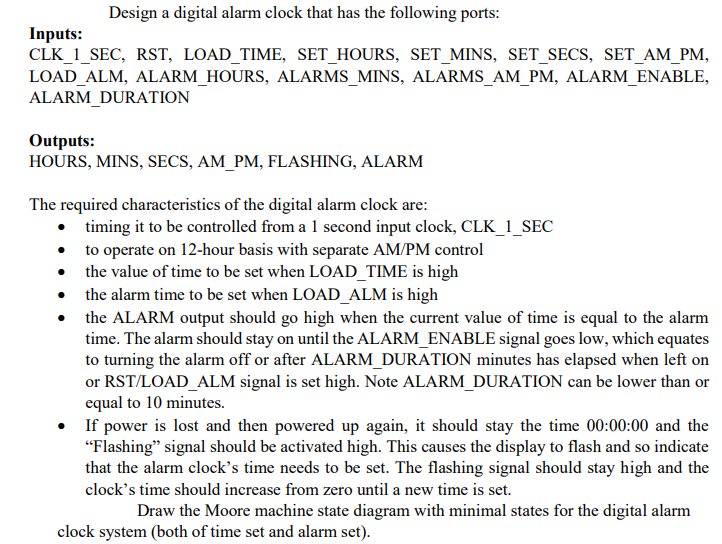
Trending now
This is a popular solution!
Step by step
Solved in 2 steps with 14 images
- What is the correct answer of ABCD This I/O technique is appropriate for network I/O devices.A. DMAB. DCAC. Programmed I/O D. Interrupt-drivenBased on the Tinkercad circuit accessible from the link below, complete the following activities:https://www.tinkercad.com/things/c1qtxCkOuBW Code is, // C++ code// const byte LED_PIN = 13;const byte METER_PIN = A4; void setup(){ pinMode(LED_PIN, OUTPUT); pinMode(METER_PIN, INPUT); Serial.begin(9600); startTimer();} void loop(){ } void startTimer(){ noInterrupts(); interrupts();} ISR(TIMER1_COMPA_vect){ digitalWrite(LED_PIN, digitalRead(LED_PIN) ^ 1);} 1. Complete the code in a way that LED blinks every 2 seconds.2. Change the startTimer method to accept a double value called timerFrequency, which representsthe frequency of the timer. Change the startTimer function so that it uses the value of this parameterto calculate and set the correct values for the OCRx and TCCRx registers.3. Use the potentiometer sensor connect to pin A4 to enable users to configure the timer frequencyBased on the Tinkercad circuit accessible from the link below, complete the following activities:https://www.tinkercad.com/things/c1qtxCkOuBW Code is, // C++ code// const byte LED_PIN = 13;const byte METER_PIN = A4; void setup(){ pinMode(LED_PIN, OUTPUT); pinMode(METER_PIN, INPUT); Serial.begin(9600); startTimer();} void loop(){ } void startTimer(){ noInterrupts(); interrupts();} ISR(TIMER1_COMPA_vect){ digitalWrite(LED_PIN, digitalRead(LED_PIN) ^ 1);} 1. Complete the code in a way that LED blinks every 2 seconds.2. Change the startTimer method to accept a double value called timerFrequency, which representsthe frequency of the timer. Change the startTimer function so that it uses the value of this parameterto calculate and set the correct values for the OCRx and TCCRx registers.3. Use the potentiometer sensor connect to pin A4 to enable users to configure the timer frequency. Plsease share the final code only.
- To drive an external actuator we need to provide an analog periodic signal y, defined as follows, y=1.5+1.5*cos(2*pi*f*t) , f=20 Hz. Your task is to generate this signal using a 16-bit digital-to-analog converter peripheral (DAC16). Answer the following questions. A. What is the maximum and minimum output voltage at the analog output? Fill in the table below by specifying min/max values and times when those values are achieved. Min/Max Value [Volts] Time [milliseconds] Min Max B. What is duration of one period of the signal y in milliseconds? What is the frequency of y? C. Let us assume that we provide a lookup table with only 10 samples for a single period of the signal y? Fill in the following table with the values for the first 4 samples (assume the first sample starts at t=0). Assume reference voltages VR+ = 3.5 V and VR- = 0V Sample t=? [ms] 1.5*cos(2*pi*f*t) 1.5+1.5*cos(2*pi*f*t) Lookup table [16-bit unsigned value in decimal] 1 2 3 4 Please HelpDetermine control words when the ports of Intel 8255 are defined as follows: [4]• Port A as an input port. Mode of the Port A is Mode 0.• Port B as an input port. Mode of the Port B is Mode 0.• Port C upper and C lower are input ports. Port A is used as input and operationmode of Port A is Mode 1.• Port B can be used as output and operates in Mode 1.In any IoT device, what is the function of an actuator? Measure a physical quantity and report it to the microcontroller. Make computation on the measured physical quantities. Manipulate the physical environment. Identify the IoT device.
- Q1) When the Timer is programmed in mode 2, TH is loaded with the 8‐bit value, then the 8051 gives acopy of it to:A. TMOD B. TLC. TF D. None of these Q2) The register used for serial transmission from and to the 8051 is the register:A. SBUF B. RIC. TI D. TMOD Q3) One way to increase the baud rate of data transfer is:A. SMOD=0 B. RI=1C. SMOD=1 D. TI=1 Q4) The transmitted bits in the case of serial communication can be:A. 4 bits B. 8 bitsC. 6 bits D. 10 or 11 bitsYour supervisor has assigned you to develop battery management system will be controlled by an independent microcontroller. The battery management system to warn the driver if battery is low. The battery charge can be read by your microcontroller either through; Digital I/O (high signal = high charge), or serial communication (data received is current charge percentage) Your microcontroller can display the current charge of the battery to the driver using a set of LED. Your proposed design should include sampling strategy for battery charge measurement and enabling/disabling car if battery is too low. Additional function such as warning lights and sound can also be incorporated. Question Based on the assigned battery management system, complete the following tasks. You should attempt to include the following microcontroller functions in your design to get full marks: I/O Timer / Counter Interrupt Serial communicationThere are two questions here. Please take resisters such ax, bx,cx,dx (16bit) or Al, bl, cl, dl(8 bit) where ever it is needed. The code should be done on “emu8086” software, because it’s the software I use so that I can run the code.
- 4.4 When silicon chips are fabricated, defects in materials (e.g., silicon) and manufacturing errors can result in defective circuits. A very common defect is for one signal wire to get “broken” and always register a logical 0. This is often called a “stuck-at-0” fault. 4.4.1 [5] <§4.4> Which instructions fail to operate correctly if the MemToReg wire is stuck at 0? 4.4.2 [5] <§4.4> Which instructions fail to operate correctly if the ALUSrc wire is stuck at 0? 4.4.3 [5] <§4.4> Which instructions fail to operate correctly if the Reg2Loc wire is stuck at 0?Assume that TA is clocked by the SMCLK running at 8 MHz. ThenCalculate the counter periods listed below,Note: Watch out for the dreaded 1 cycle errors in your calculations.a) Calculate the value (in millisec) of the shortest TA rollover period achievablein Continuous modeb) Calculate the value (in millisec) of the longest TA rollover period achievablein UP mode (remember you have a choice of clock divisor values)c) Calculate the value (in millisec) of the longest possible TA period achievablein any modeCalculate the values of the pins A0 and BHE’ and how many bus cycles are required for completing the given MOV operations. Give logical reasoning behind your answers. A) MOV DX, [12345 H] B) MOV AH, [81 H] C) MOV AX, [12340 H] D) MOV BL, [12345 H] E) MOV BX, [69 H] (F) MOV AL, [70 H]