AVERAGE Determine the equivalent force-couple system at A of the system shown on the figure on the right. F3=50 N 4.0 m 2.0 m F =200 N M1=100 N-m 3.0 m N 001 ='a
AVERAGE Determine the equivalent force-couple system at A of the system shown on the figure on the right. F3=50 N 4.0 m 2.0 m F =200 N M1=100 N-m 3.0 m N 001 ='a

International Edition---engineering Mechanics: Statics, 4th Edition
4th Edition
ISBN:9781305501607
Author:Andrew Pytel And Jaan Kiusalaas
Publisher:Andrew Pytel And Jaan Kiusalaas
Chapter3: Resultants Of Force Systems
Section: Chapter Questions
Problem 3.69RP: Determine the wrench that is equivalent to the force-couple system shown and find the coordinates of...

Related questions
Question
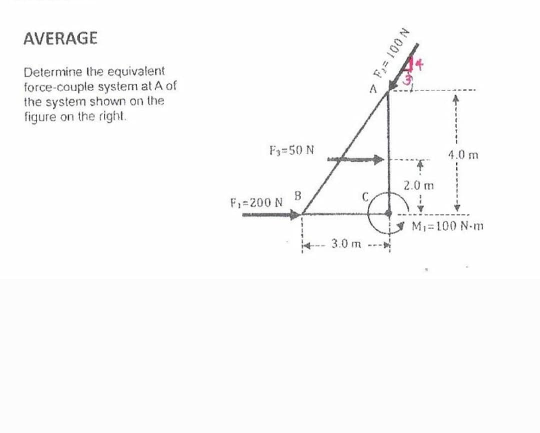
Transcribed Image Text:AVERAGE
Determine the equivalent
force-couple system at A of
the system shown on the
figure on the right.
F3=50 N
4.0 m
2.0 m
C.
F1=200 N
M1=100 N-m
3.0 m --
N 001 =4
Expert Solution
This question has been solved!
Explore an expertly crafted, step-by-step solution for a thorough understanding of key concepts.

Step by step
Solved in 2 steps with 2 images

Recommended textbooks for you
International Edition---engineering Mechanics: St…
Mechanical Engineering
ISBN:
9781305501607
Author:
Andrew Pytel And Jaan Kiusalaas
Publisher:
CENGAGE L
International Edition---engineering Mechanics: St…
Mechanical Engineering
ISBN:
9781305501607
Author:
Andrew Pytel And Jaan Kiusalaas
Publisher:
CENGAGE L