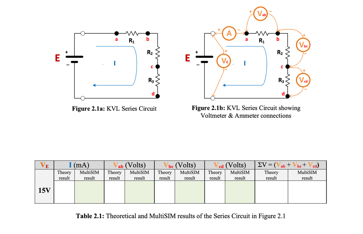
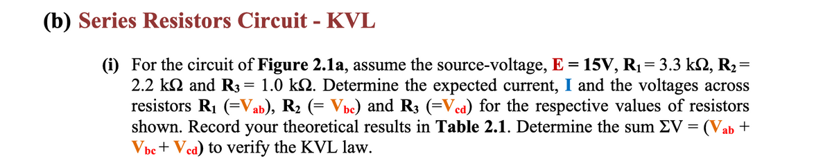
(b) Series Resistors Circuit - KVL (i) For the circuit of Figure 2.1a, assume the source-voltage, E = 15V, R₁ = 3.3 kN, R₂ = 2.2 k and R3 = 1.0 kn. Determine the expected current, I and the voltages across resistors R₁ (=Vab), R₂ (= Vbc) and R3 (=Vcd) for the respective values of resistors shown. Record your theoretical results in Table 2.1. Determine the sum EV = (Vab + Vbe + Ved) to verify the KVL law.
(b) Series Resistors Circuit - KVL (i) For the circuit of Figure 2.1a, assume the source-voltage, E = 15V, R₁ = 3.3 kN, R₂ = 2.2 k and R3 = 1.0 kn. Determine the expected current, I and the voltages across resistors R₁ (=Vab), R₂ (= Vbc) and R3 (=Vcd) for the respective values of resistors shown. Record your theoretical results in Table 2.1. Determine the sum EV = (Vab + Vbe + Ved) to verify the KVL law.

Introductory Circuit Analysis (13th Edition)
13th Edition
ISBN:9780133923605
Author:Robert L. Boylestad
Publisher:Robert L. Boylestad
Chapter1: Introduction
Section: Chapter Questions
Problem 1P: Visit your local library (at school or home) and describe the extent to which it provides literature...

Related questions
Question
100%
Transcribed Image Text:E
15V
E
a
I (mA)
Theory MultiSIM
result
result
R₁
b
R₂
с
R3
Figure 2.1a: KVL Series Circuit
ab (Volts)
Theory MultiSIM
result result
E
A
Vbc (Volts)
Theory MultiSIM
result result
a
+
VE I
R₁
cd (Volts)
Theory MultiSIM
result
result
b
R₂
C
R3
Figure 2.1b: KVL Series Circuit showing
Voltmeter & Ammeter connections
Vbc
EV = (Vab + Vbc+ Ved)
Theory
result
Table 2.1: Theoretical and MultiSIM results of the Series Circuit in Figure 2.1
MultiSIM
result
Transcribed Image Text:(b) Series Resistors Circuit - KVL
(i) For the circuit of Figure 2.1a, assume the source-voltage, E = 15V, R₁ = 3.3 kN, R₂=
2.2 k and R3 = 1.0 kn. Determine the expected current, I and the voltages across
resistors R₁ (=Vab), R₂ (= Vbc) and R3 (=Vcd) for the respective values of resistors
shown. Record your theoretical results in Table 2.1. Determine the sum EV = (Vab +
Vbc + Ved) to verify the KVL law.
Expert Solution
This question has been solved!
Explore an expertly crafted, step-by-step solution for a thorough understanding of key concepts.

Step by step
Solved in 3 steps with 2 images

Recommended textbooks for you
Introductory Circuit Analysis (13th Edition)
Electrical Engineering
ISBN:
9780133923605
Author:
Robert L. Boylestad
Publisher:
PEARSON

Delmar's Standard Textbook Of Electricity
Electrical Engineering
ISBN:
9781337900348
Author:
Stephen L. Herman
Publisher:
Cengage Learning

Programmable Logic Controllers
Electrical Engineering
ISBN:
9780073373843
Author:
Frank D. Petruzella
Publisher:
McGraw-Hill Education
Introductory Circuit Analysis (13th Edition)
Electrical Engineering
ISBN:
9780133923605
Author:
Robert L. Boylestad
Publisher:
PEARSON
Delmar's Standard Textbook Of Electricity
Electrical Engineering
ISBN:
9781337900348
Author:
Stephen L. Herman
Publisher:
Cengage Learning
Programmable Logic Controllers
Electrical Engineering
ISBN:
9780073373843
Author:
Frank D. Petruzella
Publisher:
McGraw-Hill Education

Fundamentals of Electric Circuits
Electrical Engineering
ISBN:
9780078028229
Author:
Charles K Alexander, Matthew Sadiku
Publisher:
McGraw-Hill Education

Electric Circuits. (11th Edition)
Electrical Engineering
ISBN:
9780134746968
Author:
James W. Nilsson, Susan Riedel
Publisher:
PEARSON

Engineering Electromagnetics
Electrical Engineering
ISBN:
9780078028151
Author:
Hayt, William H. (william Hart), Jr, BUCK, John A.
Publisher:
Mcgraw-hill Education,