B В D F H y C E G - 4 panels at 10 ft = 40 ft


Q: Determine the approximate axial forces, shears, and moments for all the members of the frame.…
A:
Q: QUESTION 5 Determine the force in Member AC of the Gambrel roof truss shown. Determine whether the…
A:
Q: 6 m 5 m 5 m 5000 N 45° 6 m For the truss shown, using the method of joints 1. Calculate the force in…
A: The given figure is shown below:
Q: 1. Determine the forces in each member. Indicate whether each member is in compression or tension.…
A:
Q: Evaluate the given Fink Truss using method of sections. Answer the following questions if 8= 30° ,…
A: 1. What is the reaction at A 2. What is the force in member BD 3. What is the force in member FE 4.…
Q: 200 Ib/ft 1200 Ib-ft www A В 30- ft 0.800 kip
A: The algebraic sum of the vertical forces at any section of a beam to the right or left of the…
Q: The Cantilever truss in figure below is hinged at D and E. Find the force in each member. 1000 lb B…
A: To find force in all members of the truss by method of joints
Q: 1. A simple plane truss is shown in the figure below. Use the Method of Joints only, find the force…
A: please find attached solution below
Q: For the truss shown, assume a cross sectional area of each member is 3.2 in? a. Calculate the stress…
A:
Q: 5. M 5 m 7 m 5 m 7 m
A:
Q: Determine the greatest load P the frame will support without causing the steel member BC to buckle…
A:
Q: A force F = 166 N is applied to a two-bar truss as shown and e 36 degree. Determine the value of F1,…
A:
Q: For the truss shown below, P = 9.2 kips, a = 8 ft, and b = 6 ft. Determine the force in member 3…
A: Given :- P = 9.2 kips a = 8 ft b = 6 ft To find :- force in member 3
Q: The given bridge truss supports point loads of 200kN at joints B, D, F, H, and J. The structure is…
A:
Q: 9 ft6ft6ft 9ft E F 6 ft 885 lb 960 lb 6 ft K B H 12 ft A - 6 ft--- 6 ft--
A: By method of sections, calculate the force in members JH, GH and JG.
Q: determine force member GF, FB, BC Consider the Fink truss shown in (Figure 1). Suppose that F₁ = 400…
A:
Q: 2 kN J 1 kN H 0.46 m F D 2.62 m В I A C E G 2.4 m 2.4 m 2.4 m 2.4 m
A: Method of section: The method of sections is a method for calculating the unidentified forces acting…
Q: 5 beam with the 75 mm wide flange at the bottom. Determine the moment of resistance of the section…
A: To determine the moment of resistance for given permissible stresses in tension and compression.…
Q: DETERMINE THE FORCE (Ib) IN MEMBER BD OF THE ROOF TRUSS SHOWN GIVEN THE DATA BELOW: F1 = 81 lb F2 =…
A:
Q: D F H y E G B.
A:
Q: For the figure shown below, compute the normal force in section 1. Neglect the weights of the…
A:
Q: Based on the image below, find: A. All the member forces by using the method of joints. B. Force at…
A:
Q: statics of rigid bodies
A:
Q: Using the method of joints, determine the magnitude of force (lb) in member AC of the truss shown if…
A: COnsider joint C as shown
Q: 30 kip 20 kip 18 kip F 15' H. A. C C 9' E 9' G 9'
A:
Q: Q.1)Find the tension in each of the three cables AB, AC and AD that support the weight W for the…
A:
Q: 7) Determine the force in each member of the truss shown below. C F 100 kips 1S' 1S D - 20 ァー 20
A:
Q: Determine the magnitude of force (lb) in member DB of the truss shown if P = 1199 lb, Q=2595 lb,…
A:
Q: 15 - In the plane truss system, the loading status of which is evident in the figure, the support…
A: A truss always has an axial forces in the member, and pin joint as an internal joint. This pinned…
Q: Learning Goal: To use the method of sections to determine the force in a truss member, Let point O…
A:
Q: F H 3 m E 40 kN 40 kN -4 at 3 m = 12 m FIG. P4.11
A:
Q: For the gusset plate with truss members at joint as shown in the figure, compute T force if the…
A:
Q: 200 kN 200 kN 200 kN 200 kN 200 kN D F B E 7 m 3 m 4 m A -5 m -5 m -5 m -5 m
A:
Q: Find GERF and then using the method of Joints find the forces in all members. Make sure you provide…
A:
Q: The three bars are made of A-36 steel and form a pin- connected truss. Figure 1 of 1 Part A If the…
A:
Q: The T section shown below is the cross section of a beam form by joining two rectangular pieces of…
A:
Q: A flanged wooden shape is used to support the loads shown on the bear. The dimensions of the shape…
A: To Determine (a) the maximum tension bending stress at any location along the beam, and (b) the…
Q: For the truss shown, solve the bar force of every member and indicate whether it's compression,…
A:
Q: Determine the magnitude of force (lb) in member CD of the truss shown if P = 19173 lb, a = 18.6 ft,…
A:
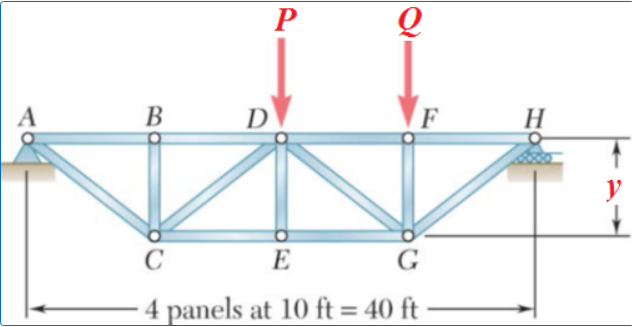
Q: P В D F H y C E G 4 panels at 10 ft = 40 ft
A:
Q: or the truss loaded and supported as shown, compute he force on each member. Again, tabulate your…
A: A truss is generally a structure that has members formed into connected triangles structures and in…
Q: The structure shown consists of two simple trusses joined by bars CF, BE, and DG. Find the force in…
A: If force is away from the joint is positive then it is tensile If force is away from the joint is…
Q: 1. Determine the force in each member of the truss shown using the method of joints. Indicate…
A: A loaded truss is given in the question and it has been asked to determine forces in all members of…
Q: 1000 lb c) Identify all zero force members. 1000 Ib d) Using the method of sections, find the forces…
A: The frame sections are analyzed by using the equilibrium conditions. Analyze each member in the…
Q: 2. Determine the force in each member of the truss loaded as shown below. State if the members are…
A: Consider the figure. Here, T is tension and C is compression.
Q: For the truss shown, use the method of sections, Each angle on the truss is 60° Note: On your FBD…
A:
Q: Q2:- Determine all forces acting on member DEF of the frame shown in Figure below:- 150 Ib/ft A в F…
A: Draw the free-body diagram of the member ABC.
Q: Calculate the force in each member of the truss shown. State whether each member is in tension or…
A:
Q: Determine the force acting on member BC of the frame shown in Ibs. P1 = 547 lbs, P2 = 640 Ibs and x…
A:
Q: Determine the force in each member for the shown truss. State whether the member is in tension (T)…
A:
Determine the magnitude of the force (lb) in member BD of the truss shown if P = 35023 lb, Q = 33321 lb, and y = 8 ft.
Round off only on the final answer expressed in 3 decimal places. Instead of units, indicate whether the force is tensile or compressive: use T if tensile and C if compressive.

Step by step
Solved in 2 steps with 2 images


- Change the complex numbers to polar form: -- 4 – 4i ( - 8i) ( - 3) √7 - i√21 --√15 + i√5Determine the nominal strength of a A36 steel column (Fy = 36 ksi), W 14 X 68 with a total length of 50 feet (both pin-end connection). W14x68 A = 20 in.^2 d = 14 in. tw = 0.415 in. bf = 10 in. tf = 0.72 in. T = 10-7/8 in. k = 1.31 in. k1 = 1.0625 in. gage = 5-1/2 in. rt = 2.71 in. d/Af = 1.94 Ix = 722 in.^4 Sx = 103 in.^3 rx = 6.01 in. Iy = 121 in.^4 Sy = 24.2 in.^3 ry = 2.46 in.f. Calculate the maximum safe load "P" in KN Two A36 16mm Thick Steel Plates Are Connected By Four Rivets With Fv=152 MPa As Shown. Given: Rivet Dia 20 mm x=100 mm
- A member is made of the following materials: steel, brass and copper, the constants are listed below:STEEL:length: 300mmcoeff. of thermal expansion: 12(10^-6)/degree Carea: 200mm^2E= 200 GPaBRASS:L= 200mmA= 450mm^2Coeff of thermal expansion: 21(10^-6)/degree CE= 100 GPaCOPPER:L= 100mmA= 515mm^2Coeff. of thermal expansion: 17(10^-6)/degree CE= 120 GPaRigid supports are located at each end of the member. What is the force exerted on the supports if the temperature increases by 6 degrees C?Channel sections are used as a purlin. The top chords of the truss are sloped at 5H to 2V. Trusses are spaced 5m on centers and the purlins are spaced 1.4m on centers. Use the properties of the channel section BELOW. Loads: (Consider all loads pass thru the centroid of the section.) Dead load = 750 Pa Live load = 1,000 Pa Wind load = 1,400Pa Wind coefficients: Windward = 0.3 Leeward = -0.5 Use Fbx=Fby=250 MPa. Determine the maximum value of the interaction equation using the load combination of 0.75(D+L+W)An aluminum alloy [E = 10,000 ksi; σY = 40 ksi] pipe (1) is connected to a bronze [E = 16,000 ksi; σY = 45 ksi] pipe at flange B. The pipes are attached to rigid supports at A and C. Pipe (1) has an outside diameter of 2.150 in., a wall thickness of 0.16 in., and a length of L1 = 6 ft. Pipe (2) has an outside diameter of 5.10 in., a wall thickness of 0.19 in., and a length of L2 = 10 ft. If a minimum factor of safety of 1.6 is required for each pipe, determine:(a) the maximum load P that may be applied at flange B.(b) the deflection of flange B at the load determined in part (a). Deflection to the right is positive.
- Help! F1: i: -27.0lbs k: -8.0 lbs F2: i: -82.0lbs M: k: -32.0 lbs*ftUse LRFD and design the tension members of the roof truss shown in Figure below. Use double-angle shapes throughout and assume 10-mm-thick gusset plates and welded connections. Assume a shear lag factor of U = 0.80. The trusses are spaced at 9 meters. Use A36 steel and design for te following loads. Metal deck : 190 Pa of roof surface Built-up roof : 575 Pa of roof surface Purlins : 145 Pa of roof surface (estimated) Roof Live Load : 960 Pa of horizontal projection Truss weight : 240 Pa of horizontal projection (estimated)1.Use LRFD and design the tension members of the roof truss shown in Figure below. Use double-angle shapes throughout and assume 10-mm-thick gusset plates and welded connections. Assume a shear lag factor of U = 0.80. The trusses are spaced at 9 meters. Use A36 steel and design forthe following loads.Metal deck : 190 Pa of roof surfaceBuilt-up roof : 575 Pa of roof surfacePurlins : 145 Pa of roof surface (estimated)Roof Live Load : 960 Pa of horizontal projectionTruss weight : 240 Pa of horizontal projection (estimated) 2. Use A36 steel and design sag rods for the truss of Problem 1. Assume that, once attached, the metal deck will provide lateral support for the purlins; therefore, the sag rods need to be designed for the purlin weight only.a. Use LRFD.b. Use ASD.
- Plz do not use gpt if u use chatgpt i will downvote you again don't use chatgptAn aluminum alloy [E = 10,000 ksi; σY = 40 ksi] pipe (1) is connected to a bronze [E = 16,000 ksi; σY = 45 ksi] pipe at flange B. The pipes are attached to rigid supports at A and C. Pipe (1) has an outside diameter of 2.300 in., a wall thickness of 0.21 in., and a length of L1 = 7 ft. Pipe (2) has an outside diameter of 4.70 in., a wall thickness of 0.17 in., and a length of L2 = 12 ft. If a minimum factor of safety of 2.2 is required for each pipe, determine: (a) the maximum load P that may be applied at flange B. (b) the deflection of flange B at the load determined in part (a). Deflection to the right is positive.Channel sections are used as a purlin. The top chords of the truss are sloped at 6H to 1V. Trusses are spaced 4m on centers. Use the properties of the channel section in the picture. Loads: Dead load = 600 Pa Live load = 800 Pa Wind load = 1,300Pa Wind coefficients: Windward = 0.25 Leeward = -0.4 Use Fbx=Fby=248 MPa. Determine the safe spacing of purlins (Use load combination of 0.75(D+L+W)