(c) Determine the total current before and after power factor correction.
(c) Determine the total current before and after power factor correction.

Power System Analysis and Design (MindTap Course List)
6th Edition
ISBN:9781305632134
Author:J. Duncan Glover, Thomas Overbye, Mulukutla S. Sarma
Publisher:J. Duncan Glover, Thomas Overbye, Mulukutla S. Sarma
Chapter2: Fundamentals
Section: Chapter Questions
Problem 2.44P: Two balanced three-phase loads that are connected in parallel are fed by a three-phase line having a...

Related questions

Question
100%
Answer letter C please
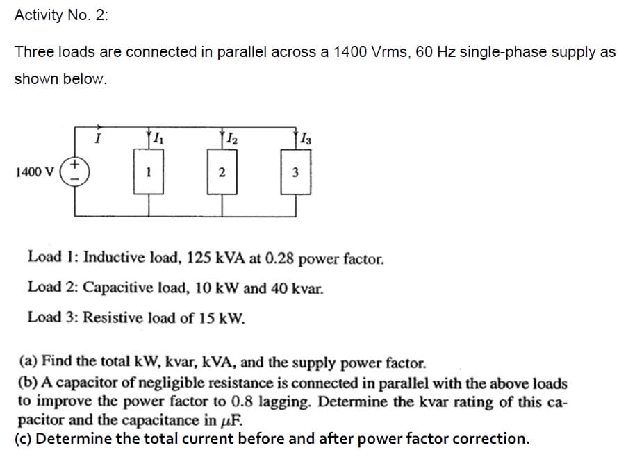
Transcribed Image Text:Activity No. 2:
Three loads are connected in parallel across a 1400 Vrms, 60 Hz single-phase supply as
shown below.
I
12
13
1400 V
1
3
Load 1: Inductive load, 125 kVA at 0.28 power factor.
Load 2: Capacitive load, 10 kW and 40 kvar.
Load 3: Resistive load of 15 kW.
(a) Find the total kW, kvar, kVA, and the supply power factor.
(b) A capacitor of negligible resistance is connected in parallel with the above loads
to improve the power factor to 0.8 lagging. Determine the kvar rating of this ca-
pacitor and the capacitance in uF.
(c) Determine the total current before and after power factor correction.
Expert Solution
This question has been solved!
Explore an expertly crafted, step-by-step solution for a thorough understanding of key concepts.

Step by step
Solved in 3 steps

Knowledge Booster


Learn more about
Need a deep-dive on the concept behind this application? Look no further. Learn more about this topic, electrical-engineering and related others by exploring similar questions and additional content below.Recommended textbooks for you
Power System Analysis and Design (MindTap Course …
Electrical Engineering
ISBN:
9781305632134
Author:
J. Duncan Glover, Thomas Overbye, Mulukutla S. Sarma
Publisher:
Cengage Learning
Power System Analysis and Design (MindTap Course …
Electrical Engineering
ISBN:
9781305632134
Author:
J. Duncan Glover, Thomas Overbye, Mulukutla S. Sarma
Publisher:
Cengage Learning