C2. In the power system network shown in Fig.3, bus 1 is slack bus with V₁ = 120° pu and bus 2 is a load bus. The line impedance on a base of 100MVA is Z₁2=0.02+j0.04 pu. After several iterations voltage at bus 2 converges to V₂ = 0.90552-6.34" pu. Determine complex power flows S12. S21 and Soss in the line. Solution: 오 V₁=1/0⁰ 1 9 Fig.3. System for question C2.
C2. In the power system network shown in Fig.3, bus 1 is slack bus with V₁ = 120° pu and bus 2 is a load bus. The line impedance on a base of 100MVA is Z₁2=0.02+j0.04 pu. After several iterations voltage at bus 2 converges to V₂ = 0.90552-6.34" pu. Determine complex power flows S12. S21 and Soss in the line. Solution: 오 V₁=1/0⁰ 1 9 Fig.3. System for question C2.

Power System Analysis and Design (MindTap Course List)
6th Edition
ISBN:9781305632134
Author:J. Duncan Glover, Thomas Overbye, Mulukutla S. Sarma
Publisher:J. Duncan Glover, Thomas Overbye, Mulukutla S. Sarma
Chapter2: Fundamentals
Section: Chapter Questions
Problem 2.18P: Let a series RLC network be connected to a source voltage V, drawing a current I. (a) In terms of...

Related questions
Question
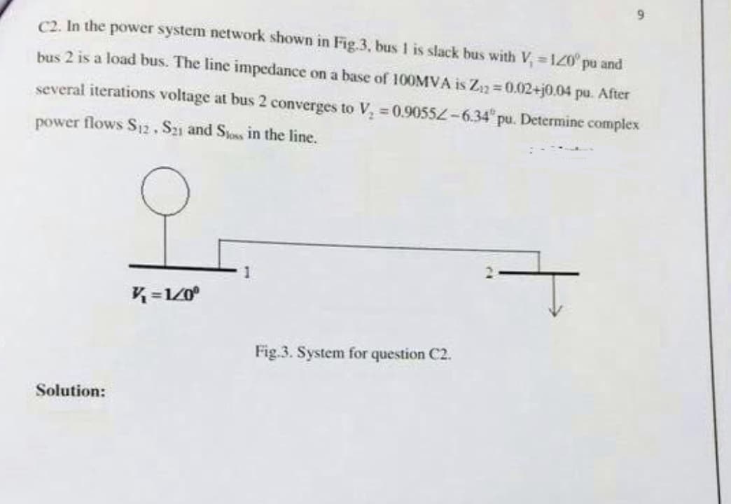
Transcribed Image Text:C2. In the power system network shown in Fig.3, bus 1 is slack bus with V₁ = 120° pu and
bus 2 is a load bus. The line impedance on a base of 100MVA is Z₁2=0.02+j0.04 pu. After
several iterations voltage at bus 2 converges to V₂ = 0.90552-6.34 pu. Determine complex
power flows S12. S21 and Sloss in the line.
9
Solution:
V=1/0⁰
Fig.3. System for question C2.
Expert Solution
This question has been solved!
Explore an expertly crafted, step-by-step solution for a thorough understanding of key concepts.

Step by step
Solved in 3 steps with 3 images

Knowledge Booster


Learn more about
Need a deep-dive on the concept behind this application? Look no further. Learn more about this topic, electrical-engineering and related others by exploring similar questions and additional content below.Recommended textbooks for you
Power System Analysis and Design (MindTap Course …
Electrical Engineering
ISBN:
9781305632134
Author:
J. Duncan Glover, Thomas Overbye, Mulukutla S. Sarma
Publisher:
Cengage Learning
Power System Analysis and Design (MindTap Course …
Electrical Engineering
ISBN:
9781305632134
Author:
J. Duncan Glover, Thomas Overbye, Mulukutla S. Sarma
Publisher:
Cengage Learning