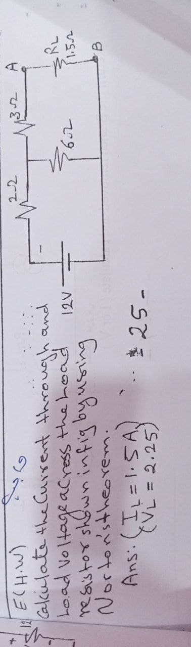
てて Cakkulate the Current through and Load Voltageacress the hoad Norton'stheorem. Ans: (IL=1.5A) TVL = 2.25)


Q: Draw the DC load line in the Graph B24 Calculate the Q point if the zero signal base current is 50…
A: Draw the dc load line of the circuit. Find the Q point if the base current is given. as per…
Q: What is the collector-emitter voltage for thetransistor if IS = 7 × 10⁻¹⁶ μA,αF = 0.99, and αR =…
A: To calculate the emitter collector voltage for the transistor. The relation of the emitter…
Q: Assume ß >> 1, VBE(on) = 0.7 volts, all npn junction areas identical, and all pnp junction areas are…
A: The given circuit is as shown below,
Q: 03 Determine operation point of the BJT in figure shown below. Assume B = 200. Rc 330 N RB Vcc 20 V…
A:
Q: Do the calculation to predict the expected theoretical output waveform of each circuit shown in…
A: As per Bartleby guidelines we are allowed to solve only one question, please ask the rest again. The…
Q: What the combined circuit resistance R,?
A:
Q: XProblem No.4 (P4). A Voltage Divider bias NPN BJT (Beta = 80) circuit is connected to a 16VDC…
A:
Q: How is the diode and zener diode in the electronic circuit and how they work? indicate the…
A: Given : Note : It is the kind notice that according to the guidelines of the company whenever we…
Q: An intrinsic semiconductor is neither a good conductor nor a good insulator. Select one: O True O…
A: A conductor is a material that effectively directs electrical flow. Most metals are acceptable…
Q: What value of saturation current IS must be used in SPICE to achieve VBE = 0.7 V for IC = 245 μA?…
A: Given data: VBE is: 0.7 V. IC is: 245 µA. T is: 27 0C The value of transconductance(K) is:…
Q: Electronics Circuit: BJT biasing A Voltage Divider bias NPN BJT (Beta = 80) circuit is connected to…
A: In this question, choose the correct options What is collector voltage? Assume VBE = 0.7V VCE sat =…
Q: XProblem No.4 (P4). A Voltage Divider bias NPN BJT (Beta = 80) circuit is connected to a 16VDC…
A:
Q: The transistor in the shown figure has the following values : VBE=0.7 V, af=0.98. a) Draw the DC…
A:
Q: Why the copper loss in the primary can be neglected, in the open circuit test
A: A transformer is an electrical machine which is used in AC circuit to either step up or step down…
Q: XProblem No.1 (PI). A fixed bias NPN BJT (Beta = 90) circuit is connected to a 16VDC supply with the…
A:
Q: XProblem No.3 (P3). An emitter bias NPN BJT with Ib= 20 microAmp, Rc= 2.7KOhms and Re= 0.68 kOhms.…
A:
Q: 169sin 377t a) What is the peak factor?
A:
Q: Determine percentage ripple and voltage drop of a six stage Cockcroft-Walton type voltage multiplier…
A:
Q: Figure 2 shows a circuit with a Bipolar Junction Transistor (BJT). Its current-voltage…
A:
Q: Q5: Full the following Blanks (Choose 10 only). 1. . . is a voltage controlled device. 2. The…
A: We are authorized to answer three subparts at a time, since you have not mentioned which part you…
Q: Determine which systems are linear. Joglr(n)1
A:
Q: loaded zener regulator, has the following parameters: Vin= 16V; the ener rated voltage 10V, series…
A:
Q: 3. For the Common Emitter circuit given in figure 3, draw the DC load line and mark the quiescent…
A: Applying KVL in B.E. loopVCC-VBE-IBRB=0Neglecting VBEVCC=IBRB⇒IB=VCCRB=301.5 M⇒IB=20μA∴…
Q: Given: 6= 100 {200N Find: Vo ac volloge @ each pt. indirated in the ekt. n/ B. io E 400N Vs 200
A:
Q: Which of the following device is made by semiconductor material and similar to 3 terminal vacuum…
A: device is made by semiconductor material and similar to 3 terminal vacuum tube
Q: For the circuit shown in Figure B23, a = 0.94, calculate the following: i. Collector current (Ic)…
A:
Q: A) what is the calculated Rin? B) Submit a plot for Vout as a function of Vin for varying Vin over 0…
A: As given in question , circuit diagram is On applying KCL at A ,…
Q: Electronics Circuit: BJT biasing A Voltage Divider bias NPN BJT (Beta = 80) circuit is connected to…
A:
Q: Electronics Circuit: BJT biasing .A Voltage Divider bias NPN BJT (Beta = 80) circuit is connected to…
A:
Q: Draw the diagram of a Zener regulated full wave power supply circuit. In your own words discuss how…
A:
Q: For the circuit shown in the Figure, consider silicon diodes with forward drop voltage of 0.7 V. If…
A: Given : The given transformer is of centre tapped transformer hence we have to take the secondary…
Q: Determine: a) dc transistor terminal VCC = +12V voltages b) hie c) Rin d) vo RC 3.3k2 R1 47k2 Vo Si…
A: Given circuit is Common emitter amplifier.
Q: Instructions Calculate the DC voltages and currents in the circuit. Find for the current emitter,…
A:
Q: Draw the wave shape of the output voltage (VOUT) of the following circuit. Assume both the Silicon…
A: Zener Diode Voltage Limiter A Zener diode is known as a breakdown diode because it operates in the…
Q: For the circuit shown in Figure B23, a = 0.96, calculate the following: i. Collector current (Ic)…
A: Here we will use current relationship for bjt .
Q: 38 - Which element shows short circuit characteristics in AC analysis of transistor circuits? A)…
A: capacitive reactance is given by Xc=1/wC c- capacitance w-Angular frequency In a.c. analysis,…
Q: XProblem No.3 (P3). An emitter bias NPN BJT with Ib= 20 microAmp, Rc= 2.7KOhms and Re= 0.68 kOhms.…
A: In this question, We need to determine the base resistance Rb R= V/I = VB /IB
Q: 4 "A diode of 600V voltage rating" means А. The peak reverse voltage is 600V. В. The maximum average…
A: 4) correct option is peak inverse voltage 600V. Usually the forward voltage drop across the diode…
Q: Explain power electronics convertors for solar systems
A:
Q: For the given circuit B=100 for silicon transistor. The value of VCE and IC. (Answers should have…
A: DC analysis of transistor is done by finding the finding the DC biasing values also known as Q…
Q: (b) Refer to fixed-bias configuration in Figure 5 below, determine: i. ii. VCE i. iv. lE V. Icsat)…
A: In this question, Fixed biasing circuit is given. Determine the base current IB , collector to…
Q: R1 9V R2 ZENER 3k (+ 1
A: we need to explain What is the advantage of using a transistor zener regulator circuit instead of a…
Q: XProblem No.3 (P3). An emitter bias NPN BJT with Ib= 20 microAmp, Rc= 2.7KOhms and Re= 0.68 kOhms.…
A:
Q: 5.46 Consider the circuit in Figure P5.46. For the transistor, B = 50. Find Is,lc. Ig, and Vo for…
A:
Q: - Q/B For the circuit below, RE=2K ohm, RC=3K ohm, VEE=4 Volt, Vcc=20Volt. Assume the transistor to…
A:
Q: 3. Determine the following parameters below and draw the DC load line. a. Ic +20 V b. IE C. VCE d.…
A: The required parameters can be calculated by using the DC analysis of the amplifier circuit.
Q: XProblem No.3 (P3). An emitter bias NPN BJT with Ib= 20 microAmp, Rc= 2.7Kohms and Re= 0.68 kOhms.…
A:
Q: For the circuit given in figure below draw the collector characteristic curves for Ig= 50, 150 and…
A: We need to draw collector characteristics . It is curve between collector current and collector to…
Q: XProblem No.4 (P4). A Voltage Divider bias NPN BJT (Beta = 80) circuit is connected to a 16VDC…
A:

Step by step
Solved in 3 steps with 2 images


- CURRENT at t= 0 ,( NEED NEAT HANDWRITTEN SOLUTION ONLY OTHERWISE DOWNVOTE).Consider the circuit segment shown in the figure below. GivenE1 = 4.91 V, E2 = 9.76 V, R1 = 29.2 kΩ, R2 = 85.4 kΩ, I1 = 35.5 µA, themagnitude of the current passing thru the second resistor is most nearlySubjection:Circuits 1please help me with solution can you slightly give me a favor about my questions? please wanna learn expand
- Consider the circuit shown in (Figure 1). Suppose that i= 1.6 AA. ind the value of vs. Express your answer to three significant figures and include the appropriate units.Calculate the current of the circuit (i.e., the current leaving from the point a Voltage is 229/9Subject: Circuits 1show your solution please
- The illumination of a drawing office 30 m x 10 m is to have a value of 250 lux and is to be provided by a number of 300 W lamps, each lamp having an output of 14 lumens per watt. CU = 0.40, MF = 0.90. Determine the number of lamps of required. Show detailed solution. No solution. No points.Use the following circuit diagram of a DC parallel circuit for calculations. Known: VAB = 14 V, R1 = 56 Ohm, R2 = 84 Ohm, and R3 = 134 Ohm. Calculate the current through path 1(I1). Keep three decimals for accuracy.Using thevenin theorem, determine the charge and discharge equivalent circuits for the Figure 4a. sketch in b and c respectively
- What is the ampacity of a #8 AWG Copper TW if there are 3 of them that are considered current carrying conductors· a conduit and the mbient temperature is 86 Degrees F? a 55 b 40 c 50 d 45It is electrical subject. Please show the complete and step by step solution.Hey May you please help me to find R(equivalence ) if R=5 ohm. If I use TinkerCad circuits( circuit simulators) to find R(equivalence) will the answer be different with the one calculated above?