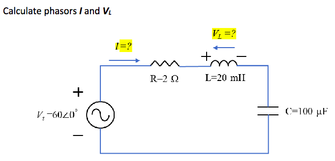
Calculate phasors / and V + V₂-6020° - R-202 V₁ = ? Į +m L=20 mII C=100 µF


Q: 3. Using any technique, solve for the voltage Vo as shown in the figure below. 30 10 M 422 M 2023 Vo…
A: Note : In the circuit value of independent source is given 2 which is not possible it should be 2vo…
Q: Problem 5 The real power absorbed by the load R₁ of 40 2 is 62.5 W in the transformer circuit.…
A:
Q: Two Coils A and B are kept in parallel plane, such that 70% of the flux produced by coil A link with…
A: In this question We need to determine the self inductance, mutual inductance and coupling…
Q: 7. (a) Calculate the mesh currents of the circuit in the figure 2K M - 24V 2 34kr 3k2 (↑) 7 MA 2 13…
A: In this question We need to determine the loop currents using the mesh analysis. Also verify the…
Q: Determine the dependent voltage Vx where V=7, R1=8, R2=8, and R3=5. V + R1 R2 ww 2Vx R3
A: Note:-Taking unit of resistance as Ohms and that of voltage source as Volts.
Q: (a) Apply the supernode technique to determine V in the circuit below. + 1ΩΣΕ. 6V Ο (-+ 2 ΚΩ • 5 ΚΩ…
A:
Q: 4. Consider the following circuit diagram, calculate total resistance; Rab. 120 12sint v 120 60 60…
A:
Q: Question 2 The unit step response of a second order system is given by: y(t)=1.2-2.7e-5wn sin(5t+ Ø)…
A: Given data, Unit step response is given as, yt=1.2-2.7e-ξωntsin5t+ϕ,=1.21-2.25e-ξωntsin5t+ϕ.
Q: 9.25 Determine the minimum states of the finite-state machine described by the state table in Figure…
A:
Q: A 40ft transmission line has a phase shift coefficient of 40radians/meter, find its wavelength.
A: We need to find out wavelength for given line .
Q: e variable resistor R in the circuit in the given figure is adjusted until it absorbs the maximum…
A: In this question We need to determine the value of load resistance RL and maximum power Pmax For…
Q: Find Vo using Source Transformation Pls show clean and complete solutio
A:
Q: Problem 2 A] Find the unit impulse response of a system specified by the equation (do not use…
A: It is given that: D2+5D+6yt=D2+7D+11xt
Q: Use phasors and nodal analysis on the circuit below to find V1 and V2
A: Given:
Q: 9.13 Convert the following power ratios to dB. (a) 3 × 10² *(b) 0.5 x 10-² (c) √2000 (d) (360)¹/4
A: Given: Power ratios: a) 3×10²,b) 0.5×10⁻²,c) 2000,d) 36014, To do: We have to convert power ratios…
Q: An AC waveform completes one cycle in 0.8 ms what is the frequency of the waveform
A: Given: Time Period, T = 0.8ms, need to calculate the frequency
Q: What are some cool/interesting applications of Fourier Series or Fourier Analysis that are not…
A: To explain: Applications of Fourier Series or Fourier Analysis that are not mentioned a lot.
Q: 3- Draw the following expression using NAND gate only X = AB + C
A: In this question We need to draw the expression of the given logic function using the NAND gate…
Q: Complete the truth table for the following Boolean functions: (a) XYZ + XYZ + XYZ (b)…
A:
Q: B/ Answer the word true or false and the 1 The electrodynamic device is used to measure the…
A:
Q: A unity feedback system has the characteristic equation shown below. Use the Routh- Hurwitz…
A:
Q: Maximum Average Power Transfer Practice Problem 11.6 In Fig. 11.12, the resistor R₁ is adjusted…
A:
Q: Determine the voltage gain for the CE amplifier in the following figure. +Voc +15 V C₁ Vin J WI R₁…
A: Voltage gain of CE amplifier ( Common emitter) Circuit :- We know for CE amplifier Av=-gm*RL Here…
Q: 1. Identify the input and output for the pivoted, adjustable mirror. Reflected Beam Source Mirror…
A: The above problem is belong to control system. In this system is collection or arrangement of…
Q: 2. Consider the interconnection shown in Fig. 2. a) What value of a is required to make this a valid…
A:
Q: The following data were obtained when a short circuit test was performed upon a 100 kVA, 2400/240…
A:
Q: 6) Determine the ^ "{F(s)}, use phase shift procedure 50 F (s) = (52+4) (5²+45 +13)
A: In this question we need to find the inverse Laplace transform of the given signal.
Q: The central processing unit of a Nehalem processor is soldered to the North or South bridge while…
A: We need to discuss the given statement .
Q: A supply voltage V(t) = 24 sin( 4000´t) [V] is applied across a R-L-C circuit shown below, where…
A: We need to find out current for series RLC circuit and voltage across capacitor and inductor.
Q: Find the values of the labeled voltage (V) and current (/) in the below circuit. Include the circuit…
A: Answer : given that diode forward voltage drop VDO = 0.7 V
Q: 2. List only one Euler's path for part (1) by drawing graphs for PUN and PDN.
A: Since you have posted the multiple questions so we are supposed to answer the 2nd one as you told.…
Q: What is the maximum number of multiplexed channels that can be achieved in a TDM circuit if all of…
A: According to the question, for the given diagram of CD 4520 as shown below What is the maximum…
Q: 4-5. Determine the moment about point B of each of the three forces acting on the beam. F₁ = 375 lb…
A: 4-5)
Q: kW
A: single phase transformer Given 200kva , % impedance =15% Copper loss=15kw. Power factor =85%…
Q: At inversion,
A:
Q: V1 -12V R1 www 22002 R2 www 10092 R3 22002 Vth VL Fig (1) 2- Required:Measure the current (IL) & the…
A: Measured current (IL) = 10.855mA Measured Voltage (VL) = 1.086V
Q: Give the other types of low-pass filters. Draw the circuit and frequency response of each.
A:
Q: Solve for the voltage Vab by finding the Thevenin equivalent circuit seen by the 140 resistor. 4 V 3…
A:
Q: 5. A telephone line has R-30 2/km, L - 100 mH/km, G-0, and C-20 µF/m. At f-1 KHz, obtain: (a) The…
A: Given- A telephone line- R=30 Ω/km,L=100 mH/km,G=0 & C=20 μF/m,f=1 KHz To Find- (a) The…
Q: +1 R1 www R6 www R8 ww R9 www R3 R5 R2 ww R4 www R10 R7
A:
Q: 1. Consider the circuit shown below. (The circles are just there to mark points on the circuit and…
A: As per the guidelines of Bartleby we suppose to answer first three subpart only for solution of…
Q: the circuit below the initial current in the inductor is zero (t0, the resistance seens by the…
A:
Q: Calculate: a) the reactance of the inductor, XL, b) the reactance of the capacitor, XC, c) the…
A: here we have to find the reactance of the inductor and capacitor and impedance of the circuit.
Q: Given the input waveform, design a circuit that can generate the corresponding output waveform. Use…
A: We need to design the circuit for given input and output waveform .
Q: a) Find the Norton equivalent of the circuit in Figure 3.125. R₁ R₂ R3 R₁ R5 R6 R₁ 1 1
A: In this question we need to find the Norton equivalent of the given circuit.
Q: Three transformers, e ach rated 25 MVA, 38. 1 /3.81 kV, are connected Star – Delta with a balanced…
A: Given: Three transformers, each rated 25 MVA, 38.1/3.81 kV, are connected Star – Delta with a…
Q: A sinusoidal signal takes 4.33 seconds to complete one cycle. What is the frequency of that signal?…
A: Given: One time period of SInusoidal waveform = 4.33 seconds Need to calculate the frequency of…
Q: Find the unknown quantities in X and v) for t> 0 in the given circuit if (0) = 10 A and L=1 H. 592…
A: In this question We need to determine the current i(t) and voltage v(t) as shown the circuit. We…
Q: 5 The phase voltages for unbalanced System are : Vb = 100 (1500 V. Vc = 80 (-100 ✓ (150⁰ Va= 100…
A: Given data:- Phase voltages:- Va=100∠30°Vb=100∠150°Vc=80∠-100°
Q: Given the input waveforms and the circuit configurations, sketch the output waveform for items (a)…
A: Given: The circuits with input wave forms as, To do: Sketch the output wave forms for both the…

Step by step
Solved in 4 steps


- What is the phasor representation of I(t)=I∘cos(ωt) at half-period? Explain. A.← B.↑ C.→ D.↗The links below show different answers. Defend yours.a. https://www.bartleby.com/questions-and-answers/what-is-the-phasor-representation-ofiticoswtat-half-period/970f7f4b-f43d-4ff2-9be5-0e61b7f4ffebb. https://www.bartleby.com/questions-and-answers/what-is-the-phasor-representation-of-it-coswt-at-half-period-o-a.-o-b.-o-c.-o-d.-x/8240eeab-f494-45d9-90b0-17809c847a75c. https://www.bartleby.com/questions-and-answers/what-is-the-phasor-representation-of-iticoswt-at-half-period-a.-b.-c.-d./47f627d0-8180-42a7-9186-2ce88402dcd9SOLVE FOR VR VL VC I P S Q. DRAW THE PHASOR DIAGRAM SOLVE USING T = V/L , PT FORMULA TO SOLVE1- Explain why the phasor and the impedance have the same angle. 2- Compare the result for utilized different frequency in same circuit. 3- Give example to utilize the RLC circuit. 4- In general, how would the phasor diagram of Figure 4.1 change if the frequency was raised? 5- In general, how would the phasor diagram of Figure 4.4 change if the frequency was lowered?
- This question from MATLAB COURSE. Demonstrate by using several values of angles x that: sin^2 (x) * cos^2 (x) =1 m.file,pleaseWhen you are converting an instantaneous current to a phasor, how does the phase angle being positive or negative affect solving the problem i.e. the representation being (wt - the phase angle in degrees) or (wt + the phase angle in degrees)?The circuit of the Figure below has Z1= 5 angle 0 , Z2= 9 angle 30 and Z3= 10 angle 80, and is supplied by a 3-phase 450-V solve for IaThe answer must be 110.29 angle -36.52
- Draw an RLC parallel circuit and draw current triangle (using phasor representations) if source phaseis 0 degree and the source current is leading source voltage 30 degrees. Draw voltage and currentphasor diagram for circuit.Can you please explain how do I write ZL from rectangular form to a phasor form (see attached the result highlighted in green)? My book says the result should be 3.142<90 Ohms which in phasor form. I don't know how this gets convertedCan someone please explain how to convert V1=-0.4220 to poloar phasor form? (V1=0.578<0)
- This question asks for the magnitudes and phase angles of V1 V2 V3 and V4, i couldn't get the right answers after a multiple tries, and i dont know where im messing up. ive been trying to set up a system of equations but it doesnt seem to be working.SUBJECT:AC CIRCUIT ANALYSIS Q#3 Determine I Total , IR1, , IC draw Phasor diagram to show the relationship between VS and I TotalIf the phasor voltage across an element is given by V=100∠120∘ and the phasor current through the same element is given by I=50∠30∘, which of the following basic circuit elements best represents this element? a. Insufficient information is given. b. Capacitor c. Some combination of these basic elements d. Resistor e. Inductor