Calculate the shear force and the maximum bending moment of beams using for the construction bridge and building. 
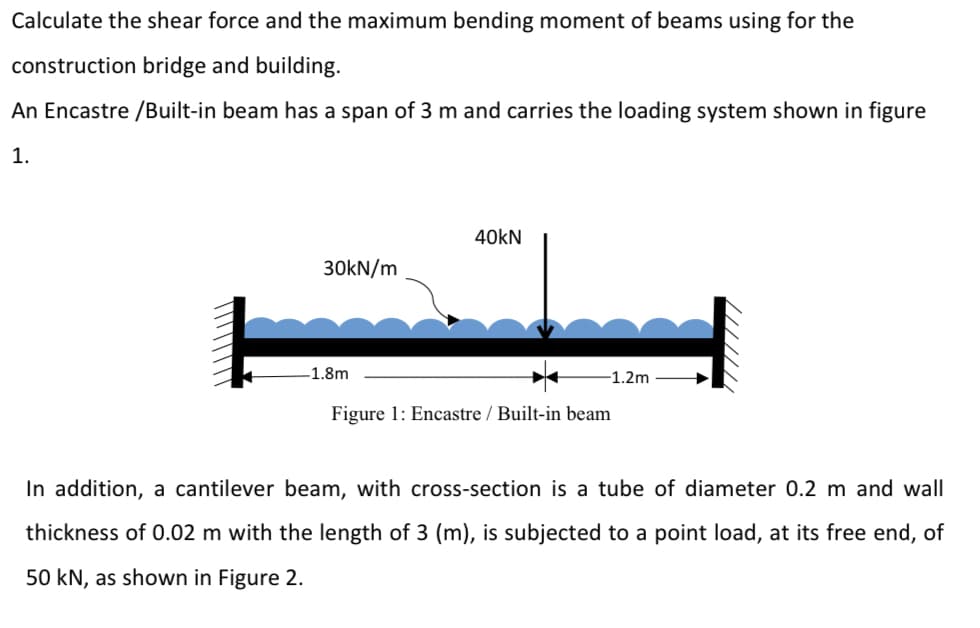
An Encastre /Built-in beam has a span of 3 m and carries the loading system shown in figure 1. 40kN 30KN/m -1.8m -1.2m Figure 1: Encastre / Built-in beam
Q: Draw the Shear Force Diagram (SFD) and Bending Moment Diagram (BMD) for a loaded simply supported…
A: Taking Moment about A, ∑MA=0;RB*6=(4*5)+(2*4)+(5*2)+(1*1)RB=(4*5)+(2*4)+(5*2)+(1*1)6RB=6.5 kN Taking…
Q: A 5 m long beam (Fig. 1) is rigidly built in at the left end and simply supported at the right end.…
A: If such end of the ruler is laying on the desk and is being held down, the ruler will bend if a…
Q: Q1) Find the values of the maximum tensile and compressive bending stresses for the simply supported…
A: As per bartleby guidelines we are allowed to solve only 1st question if multiple questions are…
Q: 1. Draw shear force and bending moment diagrams for the beam shown in figure. 30kN 2m Hello, Mr., tw…
A:
Q: A composite beam is under external loads as shown below. the internal shear force and bending moment…
A:
Q: In addition, you should be able to calculate the shear force and the maximum bending moment of a…
A:
Q: What is the bending stress occurring in a square cross section beam with a side of 8 cm, which is…
A:
Q: The variation of bending moment of a beam with distance x from one end is given by M(x) = 1-x2 .Then…
A: The slope of the bending moment diagram at a cross-section is equal to the magnitude of the shear…
Q: Problem 1 [30pts] The cross section of a rectangular beam having width b and height h is shown in…
A: Section modulus on any section is given by Z=Iy Where I=Area Moment of inertia about the axis of…
Q: The inverted T-beam supports three concentrated loads as shown in the fig?ure. Find the maximum…
A: Given that: The bending stresses are not to exceed 3.5 ksi in tension and 8 ksi in compression 1. It…
Q: Problem 1. The T-beam is subjected the load condition as shown in Figure 1. 1. Drew shear diagram of…
A:
Q: Lets consider a cantilevered beam subjected to a uniform trectangular) load with intensity 4 kN/m.…
A: Shear force diagram represents shear force at every section of the beam..Shear force at any…
Q: If a cantilever beam (one end fixed and other end free) has a cross section of 4 mm x 4 mm and a…
A:
Q: A simply supported beam with a length L = 11.3 ft and height 7 in. is bent by couples M0 into a…
A: GIVEN: Length (L)=11.3 ft Curvature (k)=0.003 /ft y=3.5 in TO FIND: The deflection at mid span and…
Q: In addition, you should be able to calculate the shear force and the maximum bending moment of a…
A: Solution:
Q: Using the flexibility method to find the bending moment distributions in the members of the L-type…
A: E same for all members Ds=(3m +r -3j) m-member =3(2) + 5 -3(3)…
Q: An encase beam with uniform distributed load shown in following figure. W= 250N/m and L= 5m. Draw…
A:
Q: A cantilever beam of length Lis subjected to a concentrated load Pat a distance of L/3 from the free…
A: Given Total length = L Concentrated load = P Load act at L/3 distance Find Deflection
Q: A rectangular section cantilever beam 200 mm wide by 400 mm deep and 2 m long carries a vertically…
A:
Q: A cantiliver of length 20 m is subjected to a point load of 35 kN and a moment of 40 kN m at its…
A: Given data: The length of the cantilever beam is L = 20 m. The point load is F = 35 kN. The moment…
Q: 15. In a simply supported beam subjected to uniformly distributed load (w) over the entire length…
A:
Q: A cantilever beam of rectangular cross- section is subjected to load at free end. If the depth of…
A:
Q: At a cross section in a rectangular beam with b=300 mm and d=500 mm, flexural reinforcement is 5T20.…
A: Calculate the area of the steel. 5T20 means,n=5 and d=20 mmthen,As=5×π4d2=5×π4202=1570.8 mm2…
Q: Task I. Draw the shearing force and bending moment diagrams for the beams shown in Figs. (1-3). Task…
A:
Q: Calculate the modulus of section of rectangle beam of breadth 120 mm and height 200 mm
A: Bending equation is given as: σy=MIσ=MyIσ=MZ Here, Z is the section modulus. Thus, section modulus…
Q: Calculate the vertical collapse of the B end of a rectangular beam with one end supported by a fixed…
A:
Q: Maximum bending stress increases with the decrease in height for a rectangular cross-section beam.…
A: GIVEN DATA STATEMENT GIVEN - Maximum bending stress increases with the decrease in height for a…
Q: QI: An -section shown in Fig. is simply supported over a span of 15 m. If the maximum permissible…
A:
Q: A rectangular beam experienced a bending moment of 100 kN-m. The width of the beam is 2 m and…
A: Given:M=100 KN.mb=2 mσb=10 MPa
Q: Draw the Shear Force Diagram (SFD) and Bending Moment Diagram (BMD) for a loaded simply supported…
A: Given data To draw the shear force and bending moment diagrams of the give nsimply supported beam
Q: Please find the question attached.
A:
Q: Home Work: 1. Draw shear force and bending moment diagrams for the beam shown in figure. 30kN 2m…
A:
Q: Calculate the vertical reaction force at A (kN). The cantilever beam and loading are shown in…
A:
Q: A cantilever beam of length 5m is loaded at the free end with a point load. The bending moment at…
A: Given data: The length of the beam is L = 5 m. The bending moment at the fixed end is M = 2.5 kN-m.…
Q: A built-in cantilever beam with a hollow rectangular cross-section is subjected to a uniformly…
A: The variation of shear force for a cantilever subjected to UDL is to be identified. Shear force…
Q: Sketch the shear force and bending moment diagram for the propped cantilever beam subjected to the…
A: Given Data: The loads acting on the cantilever beam are P each. The free-body diagram of the beam…
Q: If the "I" value of beam cross section is 6,400,000 mm4 and the maximum distance from the neutral…
A:
Q: Task I. Draw the shearing force and bending moment diagrams for the beam shown below. Task II.…
A: given: uniform distributed load on a cantelever beam of length: L =8m and a point load 50 KN is also…
Q: Draw free body diagram without writing shear and moment equation of beam shown in Figure 2.19. Give…
A:
Q: c) The same rectangular cross-section beam in Q2b is subjected to a maximum bending moment of 25,000…
A: Given:I=11.5*106 mm4d=180 mmb=23.66 (from previous part)Mmax=25000 Nm
Q: A Circular cross -Sectional beam of diameter 200 m, Simply Supported at both ends and loaded as…
A:
Q: Answer the following items. Calculate the shear force and bending moment for the beam subjected to…
A: Since you have asked multiple questions, we will solve the first question for you. If you want any…
Q: Let's consider a fixed supported beam subjected to a triangular distributed load as shown in the…
A:
Q: Draw the shear force diagram (SFD) and bending moment diagram (BMD) for the beam shown in figure. 2…
A:
Q: Maximum bending stress decreases with the increase in diameter for a circular cross-section beam.…
A: Write the equation for the bending stress. σb=32Mπd3 ............ (1) Here, The bending moment…
Q: 15. In a simply supported beam subjected to uniformly distributed load (w) over the entire length…
A:
Step by step
Solved in 2 steps with 4 images
- The hollow box beam shown in the figure is subjected to a bending moment M of such magnitude that the flanges yield but the webs remain linearly elastic. (a) Calculate the magnitude of the moment M if the dimensions of the cross section are A = 15 in., A] = 12.75 in., h = 9 in., and ey =7.5 in. Also, the yield stress is eY = 33 ksi. (b) What percent of the moment M is produced by the elastic core?.2 A ligmio.irc ii supported by two vorlical beams consistins: of thin-walled, tapered circular lubes (see ligure part at. for purposes of this analysis, each beam may be represented as a cantilever AB of length L = 8.0 m subjected to a lateral load P = 2.4 kN at the free end. The tubes have a constant thickness ; = 10.0 mm and average diameters dA = 90 mm and dB = 270 mm at ends A and B, re s pec lively. Because the thickness is small compared to the diameters, the moment of inerlia at any cross section may be obtained from the formula / = jrrf3;/8 (see Case 22, Appendix E); therefore, the section modulus mav be obtained from the formula S = trdhlA. (a) At what dislance A from the free end docs the maximum bending stress occur? What is the magnitude trllul of the maximum bending stress? What is the ratio of the maximum stress to the largest stress (b) Repeat part (a) if concentrated load P is applied upward at A and downward uniform load q {-x) = 2PIL is applied over the entire beam as shown in the figure part b What is the ratio of the maximum stress to the stress at the location of maximum moment?A cantilever beam of a length L = 2.5 ft has a rectangular cross section {b = 4in,, h = Sin,) and modulus E = 10,000 ksi. The beam is subjected to a linearly varying distributed load with a peak intensity qQ= 900 lb/ft. Use the method of superposition and Cases 1 and 9 in Table H-l to calculate the deflection and rotation at B.
- A simple beam with a W 10 x 30 wide-flange cross section supports a uniform load of intensity q = 3.0 kips/ft on a span of length L = 12 ft (sec figure). The dimensions of the cross section are q = 10.5 in., b = 5.81 in., t1= 0.510 in., and fw = 0.300 in. Calculate the maximum shear stress tjuly on cross section A—A located at distance d = 2.5 ft from the end of the beam. Calculate the shear stress rat point Bon the cross section. Point B is located at a distance a = 1.5 in. from the edge of the lower flange.A cantilever beam of length L = 2 m supports a load P = 8,0 kN (sec figure). The beam is made of wood with cross-sectional dimensions 120 mm x 200 mm. Calculate the shear stresses due to the load/"at points located 25 mm, 50 mm, 75 mm, and 100 mm from the top surface of the beam. From these results, plot a graph showing the distribution of shear stresses from top to bottom of the beam.A fixed-end b earn is subjected to a point load at mid-span. The beam has a rectangular cross section (assume that the h/b ratio is 2) and is made of wood (E = 11GPa). Find height h of the cross section if the maximum displacement of the beam is 2 mm. Calculate the displacement of the beam at the inflection points.
- A simply supported wooden I-beam with a 12-ft span supports a distributed load of intensity q = 90 lb/ft over its length (see figure part a). The beam is constructed with a web of Douglas-fir plywood and flanges of pine glued to the web, as shown in the figure part b. The plywood is 3/8 in. thick: the flanges are 2 in, × 2 in, (actual size). The modulus of elasticity for the plywood is 1,600,000 psi and for the pine is 1,200,000 psL Calculate the maximum bending stresses in the pine flanges and in the plywood web. What is q, if allowable stresses are 1600 psi in the flanges and 1200 psi in the web?Two wood beams, each of rectangular cross section (3.0 in. x 4.0 in., actual dimensions), are glued together to form a solid beam with dimensions 6.0 in. x 4.0 in. (sec figure). The beam is simply supported with a span of S ft. What is the maximum moment Mmaxthat may be applied at the left support if the allowable shear stress in the glued joint is 200 psi? (Include the effects of the beams own weight, assuming that the wood weighs 35 lb/ft3.) Repeat part (a) if Mmaxis based on allowable bending stress of 2500 psi.A hollow box beam is constructed with webs of Douglas-fir plywood and flanges of pine, as shown in the figure in a cross-sectional view. The plywood is 1 in. thick and 12 in. wide; the flanges are 2 in. × 4 in. (nominal size). The modulus of elasticity for the plywood is 1,800,000 psi and for the pine is 1,400,000 psi. If the allowable stresses are 2000 psi for the plywood and 1750 psi for the pine, find the allowable bending moment Mmaxwhen the beam is bent about the z axis. Repeat part (a) if the beam is now bent about its y-axis.
- A frame ABCD is constructed of steel wide-flange members (W8 x 21; E = 30 x ID6 psi) and subjected to triangularly distributed loads of maximum intensity q0acting along the vertical members (see figure). The distance between supports is L = 20 ft and the height of the frame is h = 4 ft. The members are rigidly connected at B and C. Calculate the intensity of load q0 required to produce a maximum bending moment of 80 kip-in. in the horizontal member BC. If the load q0 is reduced to one-half of the value calculated in part (a), what is the maximum bending moment in member BC? What is the ratio of this moment to the moment of 80 kip-in. in part (a)?-6 Calculate the maximum deflection of a uniformly loaded simple beam if the span length L = 2.0 m, the intensity of the uniform load q = 2.0 kN/m, and the maximum bending stress = 60 MPa, The cross section of the beam is square, and the material is aluminum having modulus of elasticity E = 70 GPa. (Use the formulas of Example 9-1.)A W 12 x 50 steel wide-flange beam and a segment of a 4-inch thick concrete slab (see figure) jointly resist a positive bending moment of 95 kip-ft. The beam and slab are joined by shear connectors that are welded to the steel beam. (These connectors resist the horizontal shear at the contact surface.) The moduli of elasticity of the steel and the concrete are in the ratio 12 to 1. Determine the maximum stresses r1 and xtin the steel and concrete, respectively. Note: See Table F-l(a) of Appendix F for the dimensions and properties of the steel beam.