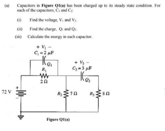
Capacitors in Figure Ql(a) has been charged up to its steady state condition. For each of the capacitors, C, and Cz: (a) (i) Find the voltage, Vị and V3. (ii) Find the charge, Qi and Q2. (ii) Calculate the energy in each capacitor. + V, - C; = 2 µF + V2 - C=3 µF he 20 2 V Figure QI(a)
Q: Create Karnaugh Map
A:
Q: piece of communication equipment has two stages of amplification with gains of 40 and 60 and two…
A: In this question we will find overall gain and input voltage....Power gain...
Q: 2.11. The normalized radiation intensity of a given antenna is given by (e)U=sin²0sin2º The…
A: The solution is given below
Q: t=0 R1 R3 В ww 1= 0 INT 1 INT 2 V1 R2 V 30 V
A:
Q: 6. A 2,200/200-V, transformer takes 1 A at the H.T. side on no-load at a p.f. of 0.385 lagging.…
A:
Q: 1. A current is given by i = 22.62sin (377t) A. Determine a) maximum value; b) rms value; c)…
A: The solution is given below
Q: Determine the logical effort g of the following compound gate: Y = (AB + CD + E)’
A: The solution is given below
Q: An FM modulator has carrier frequency of 93.2 MHz, modulated by (10 kHz) sine wave. The resultant FM…
A: As per the guidelines of bartleyby I need to answer first three subparts only So kindly repost other…
Q: Q3. Find the voltage and energy stored in an 0.4H inductor with current i(t) = 10e-³t.
A:
Q: A signal with a power level of 4 mW is applied to the input of a directional coupler. The output…
A: The solution is given below
Q: R1 R2 20 I = 2AZ30
A:
Q: Q1. Given the fixed bias circuit with VCC = 12V, RB = 240 k2, RC = 2.2 k2 and B = 75. Determine the…
A: In this question, We need to determine the values of operating point of bjt Assume forward bias…
Q: Given the flux density D = (6/r) cos(2θ) aθ C/m2, use two different methods to find the total charge…
A: The solution is given below Basic problem on charge
Q: H.W. Find Vo 127 312へ 121 2へ Vo 4A 121 Ans: (24y)
A:
Q: In order from A to D, identify whether each of A, B, C & D is positive, neutral or negative. O…
A: In this question, We need to choose the correct options Choose the electric charge if electric…
Q: The following questions refer to to a 6-pole DC generator has a simplex lap-wound armature…
A:
Q: Q2:- calculate the electrical energy.consumed by T.V. (250V) during one Month if this T.V used (3…
A:
Q: single side spe ctrum for Home worlc: s ketch the function. the same 6 - 16
A:
Q: Q2. A state machine implemented using D Flip Flops is shown in Figure 1. (a) Write down the state…
A:
Q: Calculate the voltage drop developed across a d'Arsonval meter move- ment having an internal…
A:
Q: A Wheatstone Bridge is shown in Figure Q5. Determine R3 so that the Bridge circuit is in balanced…
A: aIn Wheatstone Bridge at the point of balance i.e. VAB=Vo=0 V.Both legs have equal voltage…
Q: Q1 Find V2 in the circuit shown in figure I using: a- Mesh Current Method b- Node Voltage Method c-…
A: The various circuit analysis method are used to find the circuit parameters and the same can be…
Q: When was the first eight-track recorder introduced?
A: The first eight - track recorder introduced in the year 1965 and invented by William Powell Lear.
Q: 4. On what variable of the information signal does the distains of the side band ocillation
A: FREQUENCY MODULATION (FM): FM is a way of coding the data on the signal (such as analogue signal or…
Q: Design a voltage follower amplifier circuit with a voltage divider on it. Assume that you have 60v…
A: We need to design a voltage follower amplifier circuit with a voltage divider on it. Assuming that…
Q: A cold junction of a themocouple is at room temperature of 83°C. A votmeter connected to the…
A:
Q: 4- Describe the effect of increasing the clock frequency on the integrator output in the DM system.…
A: Please find the detailed solution in below images
Q: 1. A system has K, (i.e., position error constant) = 3. What steady-state error can be expected for…
A: This question belongs to control system . It is based on the concept of steady state error from…
Q: Question 1 Find the current, I which pass through 52 resistor by using Thevenin's equivalent…
A: In this question we have to find the value of current using thevenin theorem
Q: R1, = Rc = VL/C. Draw a complete phasor diagram showing all voltages and currents and their…
A:
Q: What type of diode is commonly used in electronic tuners in TVs? a. Schottky • b. LED O c. varactor…
A: As per our company guidelines we are supposed to answer only first question kindly repost the other…
Q: The impulse response of the system y[n]=x[n-1]+x[n-4] is O h(n]= [0 1 0 1] O h(n]= [1 1 0 0 1] O…
A: Given data, yn=xn-1+xn-4
Q: A 10KW immersion heater is placed in a pot containing two liter of water at 23°C. How long will it…
A: Given data: A 10 KW immersion heater is placed in a pot containing two liter of water. Power, P = 10…
Q: Question 2 Figure Q2 is a circuit with R; = 8 Q, C; = -j2 Q, L¡ = j4 Q, R2= 6 Q, the current source…
A: The solution is given below
Q: 1. A current is given by i = 22.62sin (377t) A. Determine a) maximum value; b) rms value; c)…
A: The solution is given below
Q: Write the expression for an AM voltage wave with the following values: Unmodulated carrier = 20 V,…
A:
Q: Required: average and effective values of the given i(t) (A) 10 2 4 6 8 10 12 14 t(s)
A:
Q: 4. Find the numerical aperture ‘θ’ of a 1.5m plastic optical fiber, if the distance from tip to…
A:
Q: 3. Determine the amplitude and phase angle of the following sinusoidal function (referred to cos).…
A: The solution is given below
Q: Question 1 Is the FSM a Mealy or Moore machine? Choose '0' for Mealy and '1' for Moore. Reset So…
A:
Q: Find the auerage and rims values for signal, the below 6.
A: In this question, We need to calculate the average value and rms value of the given waveform.
Q: 06: An FM modulator has a carrier frequency of 200 MHz, is frequency modulated by a sine wave signal…
A: NOTE- As per the rules we can answer only 3 sub-parts, please post the remaining sub-parts as the…
Q: How many NAND gates are required for implementing the function C O a. None of the above O b. 6 Oc. 4
A: Given:
Q: Design a voltage to current converter amplifier. Assume that you have 5v input voltage to the…
A: We need to design a voltage to current converter amplifier. Assuming that we have a 5 V input…
Q: 3. Assuming that (AX=10H), (BX=100H), (DX=1000H) What happens if XLAT instruction is executed?
A: NOTE- Of all the questions provided, we can provide the solution of only first question. Post other…
Q: HW1: let us determine H at P (4,0,5) in the field of an 6-A filamentary current directed inward from…
A:
Q: 2. Determine the diode is contacting or not. 5 52 ww Pp + 102 Va = 10 Y V, = 12 V-
A:
Q: What is the power rating of R? +15V Vz 1.5K, 0.6 watts b. 1.5K, 0.410 watts С. none of these d.…
A:
Q: In the circuit shown in Fig. 2.87, determine V, and the power absorbed by the 40-2 resistor. 62 20 Ω…
A:
Q: Consider the closed-loop system block diagram shown below: R(s) Ge(s) C(s) s(s+2)(s+3) S (a) Suppose…
A: As per our guidelines we are supposed to be answer the first three questions only. Kindly repost…
Step by step
Solved in 2 steps with 2 images
- Three capacitors having capacitance values of 20F,40F, and 50F are connected in parallel to a 60 - Hz power line. An ammeter indicates a circuit current of 8.6 amperes. How much current is flowing through the 40F capacitor?You are an electrician working in an industrial plant. You discover that the problem with a certain machine is a defective capacitor. The capacitor is connected to a 240-volt AC circuit. The information on the capacitor reveals that it has a capacitance value of 10 mF and a voltage rating of 240 VAC. The only 10-mF AC capacitor in the storeroom is marked with a voltage rating of 350 WVDC. Can this capacitor be used to replace the defective capacitor? Explain your answer.Switch S in in the figure is closed at time t = 0, to begin charging an initially uncharged capacitor of capacitance C = 16.1 μF through a resistor of resistance R = 20.7 Ω. At what time is the potential across the capacitor equal to that across the resistor?
- Suppose that at t=0, we connect an uncharged 10{μF capacitor to a charging circuitconsisting of a 2500-V voltage source in series with a 2{MΩ resistance. At t=40s, the capacitoris disconnected from the charging circuit and connected in parallel with a 5{MΩ resistor.Determine the voltage across the capacitor at t=40 s and at t=100 s. (Hint: You may find itconvenient to redefine the time variable to be t′=t−40 for the discharge interval so that thedischarge starts at t′=0.)You measure the capacitanceC1of a capacitor by doing thefollowing: First connect capacitorsC1andC2in series to a power sup-ply that provides a voltageVthat can be varied. The capacitance ofC2is known to be3.00mF. Then vary the applied voltageV, and for eachvalue ofVmeasure the voltageV2acrossC2. After plotting your data asV2versusV, you find that the data fall close to a straight line that hasslope 0.650. What is the capacitanceC1?A small capacitor of 100 pF is charged by a steady current of 1 µA for 1 ms. At that time, the charging circuit is disconnected. a) What is the voltage across the capacitor when the charging finishes? b) A 10 MΩ resistor is connected across the capacitor to discharge it. Sketch a graph of the voltage V across the resistor as a function of time, with appropriate numbers and units marked on the axes.
- A series circuit consisting of an inductor, a resistor, and a capacitoris open. There is an initial charge of 2 coulombs on the capacitor,and 3 amperes of current is present in the circuit at the instantthe circuit is closed. A voltage given by E(t) = 20 cos t is applied.In this circuit the voltage drops are numerically equal to thefollowing: across the resistor to 4 times the instantaneous changein the charge, across the capacitor to 10 times the charge, andacross the inductor to 2 times the instantaneous change in the current.Find the charge on the capacitor as a function of time. Determinethe charge on the capacitor and the current at time t = 10.For the circuit shown in the figure, in which the capacitor is initially fully discharged. If the source voltage V is 17 Volts, the capacitance of capacitor C is 24 mF; and the values of the resistors in Ω are: R1 = 2250 , R2 = 1071 , R3 = 2455 , R4 = 1199 and R5 = 1043 Determine the voltage across the capacitor in Volts after 15 minutes have elapsed since the circuit is energized. ..For the circuit in the figure, initially the switch S is closed in (b), until the capacitor is charged; then the switch goes to point (a) so that the battery is disconnected and the capacitor, resistor and inductor are connected in series. Once S is connected at point (a), find a) the angular frequency of oscillation for the series circuit b) write the equation for the charge on the capacitor as a function of time with the respective values of Qmax, angular frequency Wd and time T c) make the Q(t) graph showing explicitly the envelope of the exponential decay (Hint: use geogebra or an application of your choice to obtain a graph).
- 1. Inquire about the operational and geometric definitions of capacitance C. [C = = ε0 , please refer to previous lesson on capacitance.] 2. Have the students write down the meaning of each of the symbols present in the above definitions.Suppose that we have two 100-μF capacitors. One is charged to an initial voltage of 50 V, and the other is charged to 100 V. If they are placed in series with the positive terminal of the first connected to the negative terminal of the second, determine the equivalent capacitance and its initial voltage. Now compute the total energy stored in the two capacitors. Compute the energy stored in the equivalent capacitance. Why is it less than the total energy stored in the original capacitors?Two initially uncharged capacitors C 1 = 15 μF and C 2 =10 μF are connected in series. Then, a 10-V source is connected to the series combination, as shown in Figure P3.28. Find the voltages v1 and v2 after the source is applied. [Hint: The charges stored on the two capacitors must be equal, because the current is the same for both capacitors.]