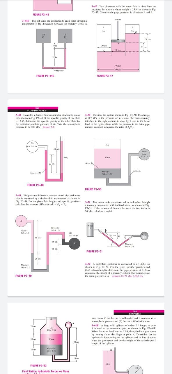
3-47 Two chambers with the same fluid at their base are separated by a pistan whose weight is 25 N, as shown in Fig. P3-47. Calculate the gage pressures in chambers A and B. FIGURE P3-43 Piston 344E Twa eil tanks are connected to each other through a manometer. If the difference between the mercury levels in Air p Air Oil Oil 50 em 10 in 30 cm 25 cm E. 30 cm 32 in Water CMereury 50 c FIGURE P3-44E FIGURE P3-47 108 FLUID MECHANICS 3-50 Consider the system shown in Fig. P3-50. If a change of 0.7 kPa in the pressure of air causes the beine mercury interface in the right column to drop hy 5 mm in the hrine level in the right column while the pressure in the brine pipe remains coustant, determine the ratio of AJA, 3-48 Consider a double-fluid manometer attached to an air pipe shown in Fig. P3 48. If the specific gravity of ene fluid is 13.55, determine the specific gravity of the other fluid for the indicated absolute pressure of air. Take the atmospheric pressure to be 100 kPa. Answer: 5.0 Air Air (P-76 kPa 40 cm Brine pipe SG-1.1 SG, Water 22 cm Aren A Area, A, Meacur sa, - 13.55 FIGURE P3-48 FIGURE P3-50 3-49 The pressure diflerence between an oil pipe and water nipe is measured by a double-fluid manometer, as shewn in Fig P3 49. For the given fluid heights and specifie gravities, calculate the pressure difference AP = P, - P 3-51 Twe water tanks are connected to each ather through a mercury manometer with inclined tubes, as shewn in Fig. P3-51. If the pressure difference between the twe tanks is 20 kPa, calculate a and o. Waner Gilyemin Waer SG- 1.26 SG =10 Oil SG -C.KK 26. cm a EWater 6l em 10 cm Merury 15 cm FIGURE P3-51 20 cm 3-52 A multifluid container is connected to a U-tube, as Mercury shown in Fig. P3-52. For the given specific gravities and fluid column heights, determine the gage pressure at A. Also determine the height of a mercury column that would create the same pressure at A. Answes: D471 KPa, 0.353 cm SG- 13.5 FIGURE P3-49 109 CHAPTER 3 sure center if (a) the car is well-sealed and it contains air at atmospheric pressure and (b) the car is filled with water. 3-61E A long, solid cylinder of radius 2 ft hinged at point A is used as an automatic gate, as shown in Fig. P3-61E. When the water level reaches 15 t, the cylindrical gate opens by turning about the hinge at point A. Determine (a) the hydrestatic force acting on the eylinder and its line of action when the gate opens and (b) the weight of the cylinder per ft length of the cylinder 70 cm Oil SG=090 30 cm Waner 90 cm Glycerin SG- 1.26 20 cm 15 em 15 FIGURE P3-52 Fluid Statics: Hydrostatic Forces on Plane
3-47 Two chambers with the same fluid at their base are separated by a pistan whose weight is 25 N, as shown in Fig. P3-47. Calculate the gage pressures in chambers A and B. FIGURE P3-43 Piston 344E Twa eil tanks are connected to each other through a manometer. If the difference between the mercury levels in Air p Air Oil Oil 50 em 10 in 30 cm 25 cm E. 30 cm 32 in Water CMereury 50 c FIGURE P3-44E FIGURE P3-47 108 FLUID MECHANICS 3-50 Consider the system shown in Fig. P3-50. If a change of 0.7 kPa in the pressure of air causes the beine mercury interface in the right column to drop hy 5 mm in the hrine level in the right column while the pressure in the brine pipe remains coustant, determine the ratio of AJA, 3-48 Consider a double-fluid manometer attached to an air pipe shown in Fig. P3 48. If the specific gravity of ene fluid is 13.55, determine the specific gravity of the other fluid for the indicated absolute pressure of air. Take the atmospheric pressure to be 100 kPa. Answer: 5.0 Air Air (P-76 kPa 40 cm Brine pipe SG-1.1 SG, Water 22 cm Aren A Area, A, Meacur sa, - 13.55 FIGURE P3-48 FIGURE P3-50 3-49 The pressure diflerence between an oil pipe and water nipe is measured by a double-fluid manometer, as shewn in Fig P3 49. For the given fluid heights and specifie gravities, calculate the pressure difference AP = P, - P 3-51 Twe water tanks are connected to each ather through a mercury manometer with inclined tubes, as shewn in Fig. P3-51. If the pressure difference between the twe tanks is 20 kPa, calculate a and o. Waner Gilyemin Waer SG- 1.26 SG =10 Oil SG -C.KK 26. cm a EWater 6l em 10 cm Merury 15 cm FIGURE P3-51 20 cm 3-52 A multifluid container is connected to a U-tube, as Mercury shown in Fig. P3-52. For the given specific gravities and fluid column heights, determine the gage pressure at A. Also determine the height of a mercury column that would create the same pressure at A. Answes: D471 KPa, 0.353 cm SG- 13.5 FIGURE P3-49 109 CHAPTER 3 sure center if (a) the car is well-sealed and it contains air at atmospheric pressure and (b) the car is filled with water. 3-61E A long, solid cylinder of radius 2 ft hinged at point A is used as an automatic gate, as shown in Fig. P3-61E. When the water level reaches 15 t, the cylindrical gate opens by turning about the hinge at point A. Determine (a) the hydrestatic force acting on the eylinder and its line of action when the gate opens and (b) the weight of the cylinder per ft length of the cylinder 70 cm Oil SG=090 30 cm Waner 90 cm Glycerin SG- 1.26 20 cm 15 em 15 FIGURE P3-52 Fluid Statics: Hydrostatic Forces on Plane

Introduction to Chemical Engineering Thermodynamics
8th Edition
ISBN:9781259696527
Author:J.M. Smith Termodinamica en ingenieria quimica, Hendrick C Van Ness, Michael Abbott, Mark Swihart
Publisher:J.M. Smith Termodinamica en ingenieria quimica, Hendrick C Van Ness, Michael Abbott, Mark Swihart
Chapter1: Introduction
Section: Chapter Questions
Problem 1.1P

Related questions
Question
i need the answer quickly
Transcribed Image Text:3-47 Two chambers with the same fluid at their base are
separated by a pistan whose weight is 25 N, as shown in Fig.
P3-47. Calculate the gage pressures in chambers A and B.
FIGURE P3-43
Piston
344E Twa eil tanks are connected to each other through a
manometer. If the difference between the mercury levels in
Air p
Air
Oil
Oil
50 em
10 in
30 cm
25 cm
E.
30 cm
32 in
Water
CMereury
50 c
FIGURE P3-44E
FIGURE P3-47
108
FLUID MECHANICS
3-50 Consider the system shown in Fig. P3-50. If a change
of 0.7 kPa in the pressure of air causes the beine mercury
interface in the right column to drop hy 5 mm in the hrine
level in the right column while the pressure in the brine pipe
remains coustant, determine the ratio of AJA,
3-48 Consider a double-fluid manometer attached to an air
pipe shown in Fig. P3 48. If the specific gravity of ene fluid
is 13.55, determine the specific gravity of the other fluid for
the indicated absolute pressure of air. Take the atmospheric
pressure to be 100 kPa. Answer: 5.0
Air
Air
(P-76 kPa
40 cm
Brine
pipe
SG-1.1
SG,
Water
22 cm
Aren A
Area, A,
Meacur
sa, - 13.55
FIGURE P3-48
FIGURE P3-50
3-49 The pressure diflerence between an oil pipe and water
nipe is measured by a double-fluid manometer, as shewn in
Fig P3 49. For the given fluid heights and specifie gravities,
calculate the pressure difference AP = P, - P
3-51 Twe water tanks are connected to each ather through
a mercury manometer with inclined tubes, as shewn in Fig.
P3-51. If the pressure difference between the twe tanks is
20 kPa, calculate a and o.
Waner
Gilyemin
Waer
SG- 1.26
SG =10
Oil
SG -C.KK
26. cm a
EWater
6l em
10 cm
Merury
15 cm
FIGURE P3-51
20 cm
3-52 A multifluid container is connected to a U-tube, as
Mercury
shown in Fig. P3-52. For the given specific gravities and
fluid column heights, determine the gage pressure at A. Also
determine the height of a mercury column that would create
the same pressure at A. Answes: D471 KPa, 0.353 cm
SG- 13.5
FIGURE P3-49
109
CHAPTER 3
sure center if (a) the car is well-sealed and it contains air at
atmospheric pressure and (b) the car is filled with water.
3-61E A long, solid cylinder of radius 2 ft hinged at point
A is used as an automatic gate, as shown in Fig. P3-61E.
When the water level reaches 15 t, the cylindrical gate opens
by turning about the hinge at point A. Determine (a) the
hydrestatic force acting on the eylinder and its line of action
when the gate opens and (b) the weight of the cylinder per ft
length of the cylinder
70 cm
Oil
SG=090
30 cm
Waner
90 cm
Glycerin
SG- 1.26
20 cm
15 em
15
FIGURE P3-52
Fluid Statics: Hydrostatic Forces on Plane
Expert Solution
This question has been solved!
Explore an expertly crafted, step-by-step solution for a thorough understanding of key concepts.

This is a popular solution!

Trending now
This is a popular solution!

Step by step
Solved in 2 steps

Recommended textbooks for you
Introduction to Chemical Engineering Thermodynami…
Chemical Engineering
ISBN:
9781259696527
Author:
J.M. Smith Termodinamica en ingenieria quimica, Hendrick C Van Ness, Michael Abbott, Mark Swihart
Publisher:
McGraw-Hill Education

Elementary Principles of Chemical Processes, Bind…
Chemical Engineering
ISBN:
9781118431221
Author:
Richard M. Felder, Ronald W. Rousseau, Lisa G. Bullard
Publisher:
WILEY

Elements of Chemical Reaction Engineering (5th Ed…
Chemical Engineering
ISBN:
9780133887518
Author:
H. Scott Fogler
Publisher:
Prentice Hall
Introduction to Chemical Engineering Thermodynami…
Chemical Engineering
ISBN:
9781259696527
Author:
J.M. Smith Termodinamica en ingenieria quimica, Hendrick C Van Ness, Michael Abbott, Mark Swihart
Publisher:
McGraw-Hill Education
Elementary Principles of Chemical Processes, Bind…
Chemical Engineering
ISBN:
9781118431221
Author:
Richard M. Felder, Ronald W. Rousseau, Lisa G. Bullard
Publisher:
WILEY
Elements of Chemical Reaction Engineering (5th Ed…
Chemical Engineering
ISBN:
9780133887518
Author:
H. Scott Fogler
Publisher:
Prentice Hall


Industrial Plastics: Theory and Applications
Chemical Engineering
ISBN:
9781285061238
Author:
Lokensgard, Erik
Publisher:
Delmar Cengage Learning

Unit Operations of Chemical Engineering
Chemical Engineering
ISBN:
9780072848236
Author:
Warren McCabe, Julian C. Smith, Peter Harriott
Publisher:
McGraw-Hill Companies, The